Lotus Elise / Lotus Exige. Instruction - part 97
Lotus Service Notes Section PL
Page 2
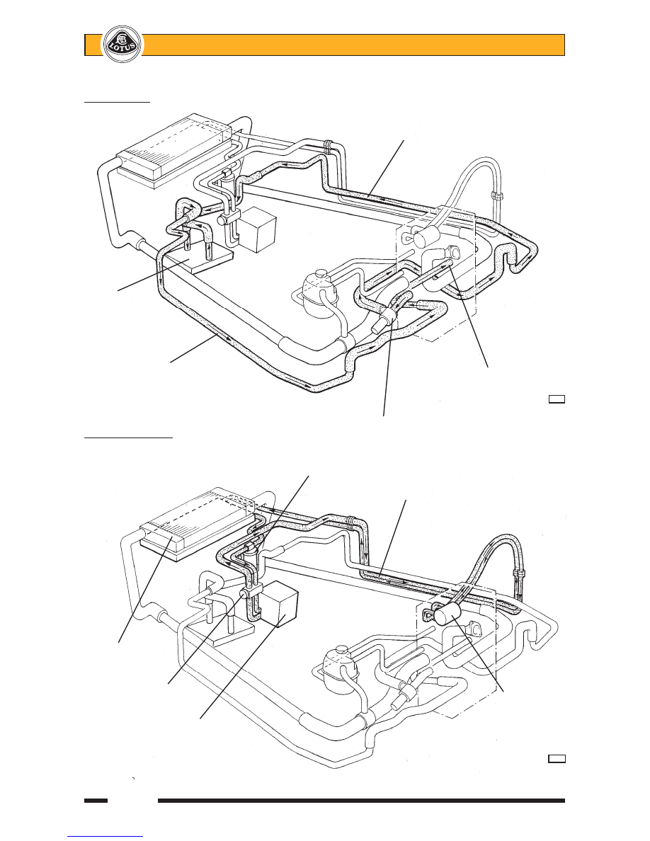
Heater Circuit
Water feed pipe along outside
of RH chassis siderail
Heater
matrix
Water return pipe
along outside of
Water return to
LH chassis siderail
engine side of
thermostat
p77c
Coolant re-circulation pump
Refrigerant Circuit
Receiver-drier
Feed & return pipes
along outside of RH
chassis siderail
Condenser
Expansion valve
Compressor
Evaporator casing
p78c