Lotus Elise / Lotus Exige. Instruction - part 67


  Index      Lotus     Lotus Elise / Lotus Exige (engine 1ZZ/2ZZ) - service repair instruction 2004 year


Search            


Content   ..  65  66  67  68   ..


Lotus Elise / Lotus Exige. Instruction - part 67


Page 3


Lotus Service Notes   


    Section LK

LK.1 - GENERAL DESCRIPTION

The 10.6 U.S. gall. (40 litre) fuel tank is fabricated from stainless steel, and is mounted within the chassis 

crossmember between the passenger compartment and engine bay, and is secured against foam mouldings 

by two support brackets from beneath.  The fuel filler neck connects with the right hand top of the tank, which 

incorporates an Onboard Refuelling Vapour Recovery (ORVR) system operating on cars prior to '06 M.Y. as 

follows:

In order to ensure that fuel vapour displaced from the tank during the course of filling is cleansed by the 

charcoal canister before venting to atmosphere, a liquid seal is used to close off the filler neck from escaping 

vapour.  The filler tube extends within the tank to within 10mm of the bottom surface, such that the end of the 

tube is submerged in liquid fuel under all normal circumstances.  A one way valve incorporated at the base 

of this fuller tube allows fuel to flow into the tank, but prevents backflow into the filler tube.  When the tank is 

being filled, displaced vapour from within the tank is vented through a Fill Level Vent Valve (FLVV) mounted 

in the top of the tank, to the charcoal canister.  Additional venting also takes place via a port in the top plate 

of the fuel pump, from where it is routed through a roll-over valve (to prevent fuel spillage in case of vehicle 

inversion) mounted on the centre top of the tank, before joining the pipe between FLVV and canister.  A 3mm 

orifice in the filler pipe just below the top surface of the tank, allows the ECU to run fuel system integrity tests 

as required by OBD3.

In order to meet LEV2 emissions criteria, the fuel system was revised for '06 M.Y.  Whilst the principle of 

operation remains unchanged, in order to reduce the potential for evaporative emissions, the roll over valve, 

and its connection with the fill level vent valve, have been moved inside the body of the fuel tank, evidence of 

this configuration being provided by a bulge in the tank top surface.  The breather port on the fuel pump top 

plate is connected back into the tank via a spigot on fuel tank top.

When the fuel reaches a specified level in the tank, a bouyant ball in the FLVV seals off the breather ap-

erture and causes a pressure rise in the filler neck to shut off the delivery discharge nozzle.  Full tank capacity 

has now been achieved.  It is 

NOT recommended to attempt to fill the tank beyond this level.

The fuel pump/fuel gauge sender unit is mounted into the left hand top surface of the tank, and includes 

a submerged turbine type pump which draws fuel through a strainer 'sock' for delivery through a non-return 

valve, integrated fuel filter and a pressure regulator valve to the outlet port.  A fuel supply pipe is clipped to the 

pump outlet port and is routed through the rear wall of the fuel tank bay, to feed the fuel rail for the four fuel 

injectors at a pressure of around 325 kPa.  The single line fuel system eliminates fuel circulation back to the 

tank, resulting in reduced fuel tank temperature and evaporative emissions.

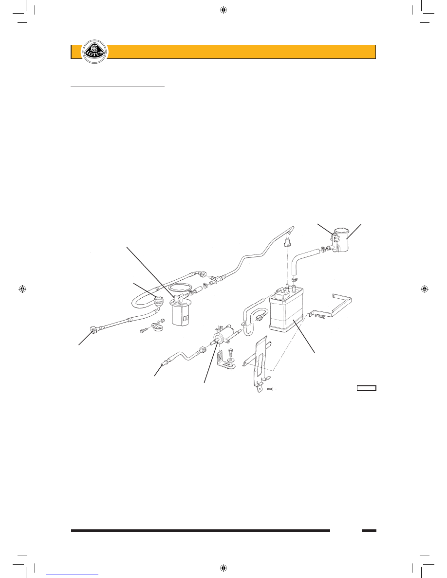
                                          Canister vent close valve            Air filter

  Float level vent valve

    Roll over valve

To fuel tank 

breather port                                            Charcoal canister

            To engine 

            intake plenum     Vapour management        


        pl4405mtc

                          valve

sn_lk_croft.indd   3

03/03/2006   11:22:28

Page 4


Lotus Service Notes   


    Section LK

When the ignition is first switched on, the engine management ECU energises the fuel pump for a period 

of about 3 seconds to prime the system before switching off.  If a signal from the crankshaft sensor indicates 

that the engine is being cranked or is running, the fuel pump feed will be maintained.  The pump is switched off 

immediately when the ignition is switched off, or about 3 seconds after a stall.  Note that if coolant temperature 

at the time of ignition switch off is over 88°C, the ECU remains powered for a period of 20 minutes to allow for 

heat soak management (see sub-section KH.5).  Re-energising the ignition during this period will not run the 

fuel pump until the ECU receives a crank signal.

A safety inertia switch is incorporated into the fuel pump electrical circuit, and operates in a severe impact 

(indicative of a vehicle collision) to switch off the fuel pump feed and minimise the fire risk.  The switch is located 

in the engine bay on the inner face of the left hand chassis siderail, and is reset once tripped, by pressing the 

rubber button on the top of the switch.

An evaporative emissions 'charcoal' canister is mounted at the right hand front of the engine bay and is 

connected to the air space inside the fuel tank via the FLVV and fuel pump top plate as previously described.  

The purge port of the canister is routed through a solenoid valve mounted on the inlet manifold, to a port on 

the intake plenum.  The evaporative emissions control system prevents untreated fuel vapour from the tank 

reaching the atmosphere, by absorbing the tank vapour in a bed of activated charcoal in the canister.  When 

the engine is running, the engine management ECU opens the Vapour Management Valve (VMV) and allows 

intake manifold depression to draw fresh air through the canister, purging absorbed fuel from the charcoal, and 

consuming the resultant vapour in the normal combustion process.  In this way, the charcoal bed is 'cleaned' 

ready to absorb more tank vapour.  

LK.2 - FUEL FILLING

Fuel Requirement

USE UNLEADED PREMIUM GRADE GASOLINE.

Use only unleaded gasoline meeting ASTM specifications.  Use of fuels not meeting ASTM specifications 

could cause poor performance and increase emissions.

For optimum vehicle performance and fuel economy, the use of super or premium unleaded gasoline, with 

a minimum octane rating of 91 (RON+MON)/2 is recommended.  Where super or premium fuel is not available, 

the Elise will operate satisfactorily on unleaded gasoline having a minimum rating of 87 (RON+MON)/2, but 

vehicle performance and economy will be reduced.  Using fuel with a lower octane rating may cause knocking 

(pinking) which, if severe, can cause serious engine damage.  Light knocking may occasionally be heard for 

short periods when accelerating or driving up hills, and this should cause no concern, although using a lower 

gear would be advised.  If, however, persistent heavy knocking is heard when using the specified fuel, the cause 

should be ascertained without delay.

The use of good quality fuels containing proper detergent additives is advised for good performance and 

emission control. 

Do NOT use leaded fuel: damage caused by the use of leaded or other improper fuel is not covered by 

              Fuel pump inertia switch


    ohs137

sn_lk_croft.indd   4

03/03/2006   11:22:28

Page 5


Lotus Service Notes   


    Section LK

the New Vehicle or Emission Control System Warranty.  Leaded fuel will damage the oxygen sensor as well 

as contaminating the catalytic converter, the effectiveness of which decreases after as little as one tankful of 

leaded fuel. 

Gasolines Containing Alcohol - Some gasolines sold at service stations contain alcohol although they may not 

be so identified.  Use of fuels containing alcohol is not recommended, unless the nature of the blend can be 

determined as being satisfactory.

Gasohol - A mixture of 10% ethanol (grain alcohol) and 90% unleaded gasoline may be used in the Lotus 

Elise.  If driveability problems are experienced as a result of using gasohol, it is recommended that the vehicle 

is operated on gasoline.

Methanol - Do not use gasolines containing methanol (wood alcohol).  Use of this type of alcohol can result in 

vehicle performance deterioration and damage to critical parts in the fuel system.  Fuel system damage and 

vehicle performance problems, resulting from the use of gasolines containing methanol, may not be covered 

by your vehicle warranty.

Fuels Containing MMT - Some North American fuels contain methylcyclopentadienyl manganese tricarbonyl 

(MMT), which is an octane enhancing additive.  Such fuels may damage the emission control system and are 

NOT recommended.

Diesel - The Lotus Elise will not operate on diesel fuel.

Fuel Filling 

WARNING:  Be aware of the danger of explosion when dealing with petrol and its attendant fumes.  Be-

fore stopping at a filling station, switch off mobile phones, ensure that all cigarettes are extinguished 

and that no naked flames or other potential ignition sources are present.  Switch off the engine before 

refuelling.

Filler Cap:  The fuel filler cap is located in the right hand rear quarter panel, concealed beneath a spring loaded 

flap.  To remove, pull open the flap and turn the cap anticlockwise.  As the cap is turned, any slight pressure dif-

ferential between the tank and atmosphere will be released, and a brief hiss may be heard, which is completely 

normal.  Note that the cap is tethered by a short strap to protect against loss.


To refit, place the cap into the filler neck and turn clockwise until the ratchet mechanism clicks several 

times.  Push the flap closed. 

Filling Procedure:  Insert the pump nozzle fully into the neck, and fill until the auto-shut off mechanism is trig-

gered.  Do not attempt to ‘brim’ the tank to the top of the filler neck, as expansion of the fuel due to temperature 

change (cold underground fuel storage) may cause flooding of the fuel tank breather system charcoal canister, 

or spillage of fuel.  The useable fuel tank capacity is 10.6 U.S. gall. (40 litres).

LK.3 - PRECAUTIONS

The fuel line between pump and injector rail, and the injector rail itself, contain pressurised fuel both when 

the ignition is switched on, and for a period after switching off.  This feature aids engine starting by reducing 

the time needed to build up operating fuel pressure, and by inhibiting the formation of vapour pockets in the 

supply line of a stopped hot engine.

WARNING:

i) 

To minimise the risk of fire and personal injury, relieve the fuel system pressure before servicing 

any part of the fuel supply circuit.  See ‘Fuel Pressure Relief Procedure’ below.

ii)  To reduce the possibility of sparks occurring when a fuel line is disconnected, or when fuel vapour 

is present, the negative battery cable should be disconnected before work is commenced. 

iii)  When fuel lines are disconnected, absorb any escaping fuel in an absorbent cloth and dispose of 

safely. 

sn_lk_croft.indd   5

03/03/2006   11:22:28

Page 6


Lotus Service Notes   


    Section LK

Fuel Pressure Relief Procedure

This procedure should be used prior to disconnecting any part of the fuel line.  

Pull out the fuel pump fuse (on the left 

hand side of the engine bay bulkhead, as 

shown), start the engine, and run until it 

stops from starvation.  Crank the engine 

for a further few seconds.

If the engine is a non-runner, pull out the 

fuel  pump  fuse,  and  crank  the  engine 

for 20 seconds to minimise residual fuel 

pressure.

Disconnect the battery.


It  is  recommended  first  to  release  the 

quick fit connector located to the rear of 

the coolant header tank:

Release the retaining clip securing the 

pipe joint to the header tank bracket.

Slide the orange coloured safety lock to 

allow  access  to  the  connector  release 

buttons.

Surround the pipe joint with a shop towel 

to absorb fuel contained in the pipework 

before pressing the release buttons and 

separating the joint. 


WARNING: Be aware of the possibility of full 

pressure retention in the fuel line caused by 

a system fault.

Before re-making the joint, ensure that the or-

ange safety lock is fitted onto the pipe connector 

in the orientation shown in the illustration.

Push the male pipe end fully into the female 

connector until a click is heard.  Pull on the pipe 

to ensure complete engagement.

Slide the orange safety lock over the connector 

to prevent accidental pressing of the release 

buttons.

Secure the pipe/connector using the pipe  clip 

on the header tank bracket.

LK.4 - FUEL TANK

The 10.6 U.S. gall. (40 litre) stainless steel fuel tank is mounted within the chassis crossmember between 

the passenger compartment and engine bay, and is secured against foam mouldings by two support cradles from 

beneath.  The fuel filler connects with the right hand top of the tank, and the fuel pump/fuel gauge sender unit 

is mounted into the left hand top surface.  A removeable panel is provided in the top of the chassis crossmem-

ber in the cabin, and provides access to the fuel pipe connections and harness connector.  If the pump/gauge 

sender unit is to be replaced, the tank must first be removed from the chassis. 


Fuel pump 

fuse (20A)


                ohs136


                        Fuel pipe to 

Orange                    engine

safety lock

Fuel pipe 

from tank

                          Release

L64

                         button

sn_lk_croft.indd   6

03/03/2006   11:22:29


Content   ..  65  66  67  68   ..