Lotus Elise / Lotus Exige. Instruction - part 66


  Index      Lotus     Lotus Elise / Lotus Exige (engine 1ZZ/2ZZ) - service repair instruction 2004 year


Search            


Content   ..  64  65  66  67   ..


Lotus Elise / Lotus Exige. Instruction - part 66


Lotus Service Notes                                 Section KH

Page 9

exchanger to the heater water return pipe.  This device transfers heat from the engine coolant to the oil after a
cold start, and conversely, in conditions of high oil temperature transfers heat from the oil to the coolant.

Front Mounted Air/Oil Coolers

On cars so fitted, front mounted oil/air radiators are mounted ahead of each front wheel arch and fed with

air from intakes either side of the main engine radiator intake in the body nose.  'Single oil cooler’ cars are
equipped with an oil cooler ahead of only the LH front wheel, but use the same hoses as twin oil cooler cars,
with a joiner union attached to a bracket in place of the symetrically opposite RH cooler.

On all cars with front mounted oil cooler(s), the oil/water heat exchanger is replaced by a sandwich plate

incorporating oil take-off feed and return unions, with the redundant coolant hoses interconnected by a 'U' pipe.
A thermostat incorporated into the sandwich plate begins to open at 72ºC, and is fully open at 80ºC.  When
open, oil is directed from the sandwich plate via a flexible hose within the RH sill panel, over the front wheel
arch liner to the top connection on the RH oil cooler (or joiner union on single oil cooler cars).  From an outlet
union at the bottom front of the cooler (or joiner union), another hose runs beneath the crash structure to the
bottom of the LH cooler, from the top of which oil is returned via a third hose, running through the LH sill, back
to the return union on the sandwich plate.

Each cooler is secured by a two stud bracket to the side of the crash structure, and positioned immedi-

ately ahead of the engine radiator mounting panel side extensions, which incorporate airflow apertures and
additional deflector panels on their front surfaces.  Louvres in the wheelarch liner front sections allow air to
exhaust from the coolers into the wheelarches.
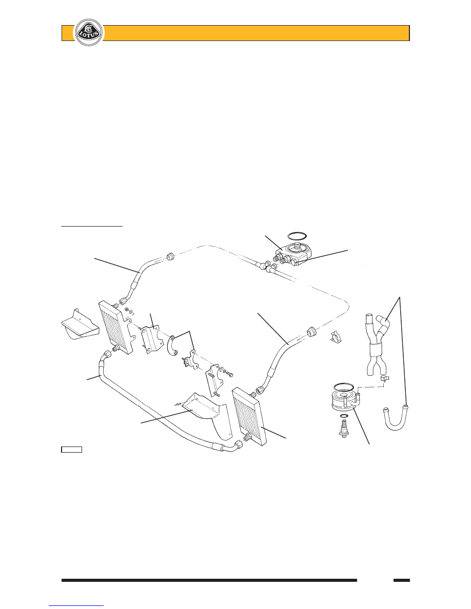
Oil Cooler Layout

Oil cooler
sandwich plate

Cooler feed hose

Oil cooler

in RH sill

thermostat

Heat exchanger

Cooler

hoses or by-pass

mounting

Cooler return hose

plate

in LH sill

Nut plates

Cooler
inter-
connection
hose

Air deflector
panel

LH oil

 pl4603mt

cooler

Oil/water
heat exchanger


 Lotus Service Notes                                 Section KH

Page 10

Procedure for conversion from single to twin front mounted oil coolers

Parts Required

Part Number

Qty

Oil Cooler, RH, incl. foam seal

A120K0020F

 1

Duct, oil cooler, RH

- Elise

A120B0090F

 1

- Exige

A122B0194F

 1

Big Head Pop Rivet, duct fixing

A089W6297F

 3

1.

Remove the front clamshell (refer to sub-section BR.6).

2.

Disconnect oil cooler hoses from joiner union ahead of RH front wheel using 2 off 1 1/8" spanners, and
plug hose ends to minimise oil loss.

3.

Remove hose joiner bracket and secure new oil cooler, with its pre-applied sealing foam, to mounting
bracket using existing fixings.  Torque tighten to 22 Nm.

4.

Fit hoses to oil cooler.  When tightening the union nut it is essential that the oil cooler union is held
using a 15/16 in. open end spanner
 whilst torque tightening the hose union nut (1 1/8") to 40 Nm.
Failing to follow this procedure may result in damage to the oil cooler.

5.

Start the engine and check for oil leaks.

6.

Secure the new cooler duct with the three big head rivets to the radiator duct and refit the front clamshell.

Oil Cooler Circuit Bleeding

When carrying out routine oil changes,

the oil quantity contained in the twin oil cool-
ers and associated pipework is not disturbed
and is considered perfectly satisfactory for
routine maintenance operations.  In instances
of major engine failure where the oil system
may be contaminated with metallic debris, all
oil cooler lines should be thoroughly flushed
out and the oil cooler radiators replaced.

If the oil cooler circuit is drained or re-

placed, the following procedure should be
adopted to fill the cooler system before start-
ing the engine:

1.

Attach a tube to the bleed nipple on the
sandwich plate between oil filter and
engine block, and lead into a catch tank.
Open the bleed nipple.

2.

Disconnect the outlet hose from the top
of the LH oil cooler, and pour engine oil
into the cooler until oil reaches the bleed
nipple (approx. 2.5 litres).
Close the bleed nipple, tightening to 8 Nm.

3.

Connect the LH cooler outlet hose and tighten to 40 Nm.

4.

Add a further 0.7 litres of oil into the engine to accommodate the volume of the return hose between LH
oil cooler and engine.

5.

After starting the engine, restrict running to idle speed for a minimum of 5 minutes, to allow the oil cooler
lines to be purged of air.  Stop engine and re-check oil level.

Sandwich
plate bleed
nipple

         e228

Page 1


Lotus Service Notes   


    Section LK

FUEL SYSTEM

SECTION LK  -  ELISE for North America

                                                       Sub-Section   Page

    General Description                                      LK.1      3

    Fuel Filling                                            LK.2      4

    Precautions                                           LK.3      5

    Fuel Tank                                            LK.4      6

    Fuel Pump/Sender Assembly                                LK.5      9

    Charcoal Canister                                        LK.6      10

    Fuel Tank Pressure Test                                    LK.7      11


sn_lk_croft.indd   1

03/03/2006   11:22:27

Page 2


Lotus Service Notes   


    Section LK


Canister vent


Fuel System Layout - prior '06 M.Y

. 


Fuel fi

ller neck 


close valve


Fuel rail


Pipe to inlet


manifold


Tank breather 


connection


Quick fi


connector


Fuel feed


pipe


Charcoal canister


Vapour Management


Valve (VMV) 


Fill Level V

ent V

alve (FL

VV)


Roll over valve 


Fuel tank


em208b


Fuel pump

sn_lk_croft.indd   2

03/03/2006   11:22:27


Content   ..  64  65  66  67   ..