Lotus Elise / Lotus Exige. Instruction - part 13


  Index      Lotus     Lotus Elise / Lotus Exige (engine 1ZZ/2ZZ) - service repair instruction 2004 year


Search            


Content   ..  11  12  13  14   ..


Lotus Elise / Lotus Exige. Instruction - part 13


Lotus Service Notes                                  Section BR

Page 7

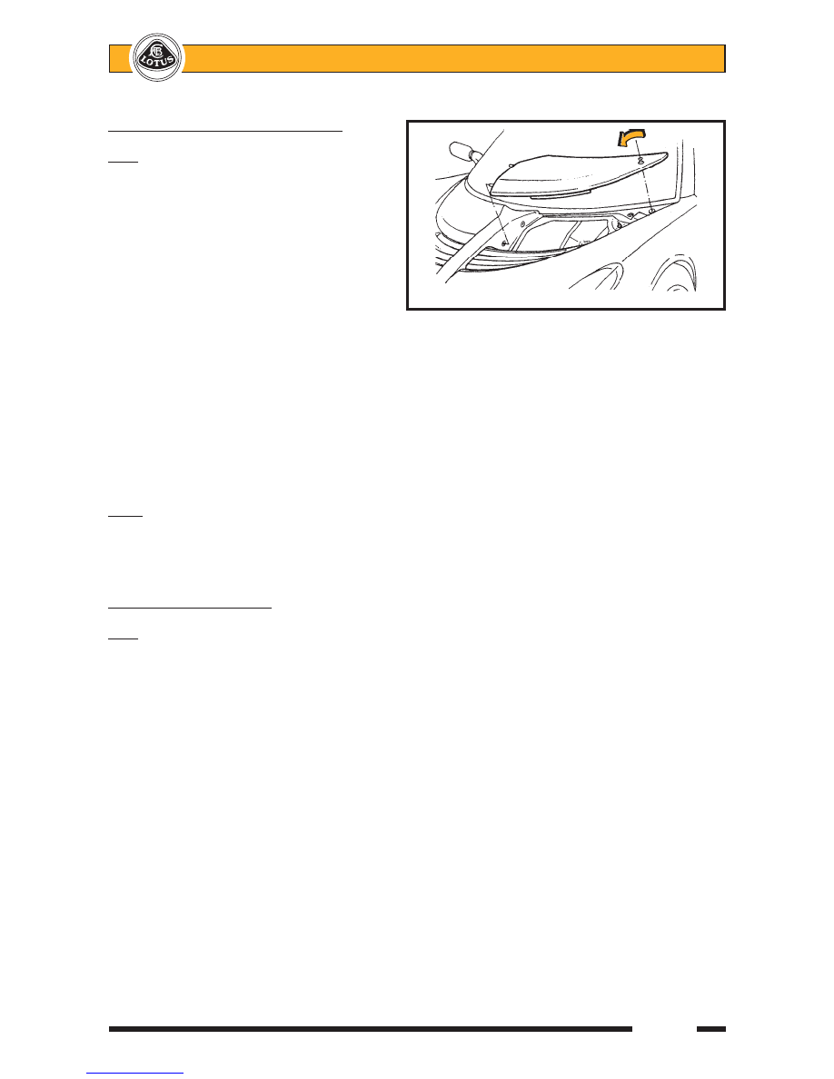
BR.3 - FRONT BODY ACCESS PANELS

Elise

Two removeable, body colour compos-

ite panels are provided in the front body to
allow access to the front fusebox and brake
fluid reservoir.
To remove an access panel:  Use the hexago-
nal key supplied in the vehicle tool kit (in the
battery cover rear pocket), to release the sin-
gle threaded fastener securing the outboard
corner of the panel, and withdraw the panel
from the two locating holes in the front body
spine.  Guard against the lightweight panel
being blown away and damaged by a strong
wind.
To refit a panel:   Hook the extended lip on the front edge of the panel beneath the rear edge of the louvre panel
before engaging the two locating pegs on the inboard side of the access panel with the grommeted holes in the
front body spine.  Fit the single screw at the outboard corner of the panel into the captive nut in the body, taking
care not to cross-thread or overtighten the screw.  Re-stow the hexagonal key in the tool kit.

Note that the outboard fastener uses a mounting plinth adjustable in height to allow optimum panel

alignment to be achieved.

WARNING:  Ensure the access panels are refitted and properly secured before driving.

Exige

The access panels on the Exige model are shorter front to back than those of the Elise, and are retained

by three socket head screws, the outermost of which features an adjustable plinth to allow panel height adjust-
ment.

BR.4 - ENGINE COVER LID

Elise

The engine cover/boot lid is moulded from glass fibre composite and incorporates 4 engine cooling outlet

grilles secured by double sided tape and plastic rivets into recessed apertures.  Two hinges are used to attach
the lid to the rear bulkhead, with stud plates fixing the hinges to the bulkhead from the engine bay side, and the
nuts accessible from the cabin after removal of the rear bulkhead trim panel.  A single, key operated latch
mechanism secures the lid to a striker pin mounted on the clamshell engine/boot bulkhead.  The latch is
released by inserting the ignition key into the lock and turning clockwise, the lock barrel being connected to the
latch mechanism by a short link rod.  When the latch is released, a spring plunger will lift the lid sufficiently to
allow it to be raised fully by hand.  Support the lid by inserting the prop provided on the boot bulkhead into the
slotted plate adjacent to the latch mechanism.  The spring plunger also operates a micro-switch for the alarm
system, and is protected from exhaust manifold heat by a steel shield.

When closing the lid, fully engage the latch mechanism by pressing down on the cover only immediately

above the latch.  Note that the lock mechanism plastic cover plate on the underside of the engine lid, serves
also to channel any water ingress from around the lock into the engine bay.  Drain holes are provided in the
gutter surrounding the engine bay, with a collector and drain tube fitted at the rearmost extremity.

On USA models, an fluorescent emergency internal release handle is fitted on the underside of the lid to

facilitate the escape of a trapped child.

To remove the engine cover, release the cover from the two identical hinges.  Note that the hinges also

serve to clamp the clamshell front edge to the cabin rear bulkhead.

Beware that the engine cover is locked whenever it is closed, and always requires the use of the ignition

key to release.  Owners should be made aware of the importance of having a spare key available in case of
inadvertently locking the keys in the boot.


REMOVING ACCESS PANEL

ohs93


Lotus Service Notes                                  Section BR

Page 8

Exige

On Exige models, the double skin, moulded composite tailgate panel, mates with an air intake duct in the

clamshell and roof panel to admit cooling air into the engine bay, and also features seven steel mesh grilles to
allow for the exhaustion of hot air.  The tailgate panel uses extruded alloy hinges at its front edge, anchored to
the underside of the clamshell, and is provided with a gas spring strut to support the lid in the fully open
position.  The latch mechanism is mounted on the boot bulkhead, where it, and an adjacent alarm plunger
switch are protected by a steel heat shield.  The latch is operated by a cable release from a lever handle
mounted outboard of the driver's seat back.

A rear aerofoil with integrally moulded support struts, is secured to the rear end of the tailgate and

transfers loads via adjustable abutments into the boot bulkhead and body structure.

Theaded insert
in engine lid

Engine lid hinge

Studplate clamping hinge &
clamshell to bulkhead

        b318

Nut inside cabin

Tailgate release handle

    ohs141


Lotus Service Notes                                  Section BR

Page 9

BR.5 - DOOR HINGE COVER PANEL

A separate glass fibre composite body panel is used to fill the area beween the door and wheelarch, and

uses threaded fasteners to attach to the rear of the clamshell, top of the sill and bottom inboard edge of the sill
panel.

To remove a door hinge cover panel:

-

From beneath the sill, remove the two fixings securing the bottom edge of the hinge panel to the sill.

-

Remove the filler panel concealing the fixing securing the hinge cover to the door sill recess, and remove
the fixing.

-

Remove the wheelarch liner and remove the single screw securing the door hinge cover panel to the
clamshell.

-

Release the repeater lamp harness and withdraw the panel.

BR.6 - FRONT CLAMSHELL

The front clamshell is a bonded assembly of several glass fibre composite mouldings incorporating both

front wings, the front access aperture, radiator air intake and headlamp housings.  The clamshell is secured to
the windscreen frame, radiator mounting panel and other panels using threaded fasteners for ease of removal
and to facilitate service access and body repair.

To Remove Front Clamshell
1.

Remove both front body access panels.

2.

Remove both front wheelarch liners;

No fixing used

Remove front

in this position

top fixing

Door
sill
filler
panel

Door hinge
cover panel

Hinge cover to
door sill fixing

Hinge cover to

        b231

sill underside


Lotus Service Notes                                  Section BR

Page 10

3.

From inside each wheelarch, remove the single screw securing the top edge of the door hinge cover
panel to the clamshell.  On cars fitted with front mounted oil coolers, release the hoses from any clamshell
clips around the top of the wheelarch.

4.

Via each door aperture, remove the single fixing securing a bracket at the top rear corner of the clamshell
to the base of the windscreen pillar.

5.

Remove the fixing at each side securing the clamshell to the bottom of the windscreen frame.

6.

Elise: Remove the two nuts securing the clamshell spine bracket to the wiper motor bracket extension.
Exige: Remove the two nuts and bolts securing the clamshell spine to the wiper motor extension bracket,
and the two screws each side securing the clamshell channel to the radiator air deflector panel.

7.

If fitted, remove the single fixing at the bottom front of each wheelarch, securing the clamshell to the
radiator panel extension (not used on oil cooler cars).

8.

Remove the headlamp cover/mask assembly from each side by releasing the three socket head screws
inside the wheelarch.  Remove the clamshell fixing at the front of each headlamp housing.  Release the
headlamp harnesses, and feed through the clamshell hole.  Disconnect the aerial lead(s).

9.

Beneath the nose, release the screws fixing the front lower edge of the clamshell to the alloy undertray.

10.

Lift the clamshell from the car.  Note any spacing washers or shims fitted at any fixing point.

Clamshell spine to

Fixing inside

wiper motor bracket

headlamp
housing

Clamshell lower front

Fixing to

edge to undertray

windscreen
frame

Fixing to base of
windscreen pillar

Fixing to radiator mounting panel
(not used with oil coolers)

Fixing of door hinge

        b316

cover panel to clamshell


Content   ..  11  12  13  14   ..