Lotus Elise / Lotus Exige. Instruction - part 9


  Index      Lotus     Lotus Elise / Lotus Exige (engine 1ZZ/2ZZ) - service repair instruction 2004 year


Search            


Content   ..  7  8  9  10   ..


Lotus Elise / Lotus Exige. Instruction - part 9


Page 10


Lotus Service Notes   


    Section BQ

It is not generally practical to remove a bonded panel intact, for later refitment.  Consequently, when 

necessary, the panel can be cut away for better access to the bonded joint. It is not necessary to remove all 

traces of sealant from the joint faces on the remaining panels or chassis, but any remaining sealant must be 

securely bonded and no thicker than 1 mm or the fit and joint gaps will be upset. It is essential always to follow 

the cleaning/priming/bonding operations meticulously if sufficiently strong and durable bonds are to be obtained. 

Always use the specified materials.

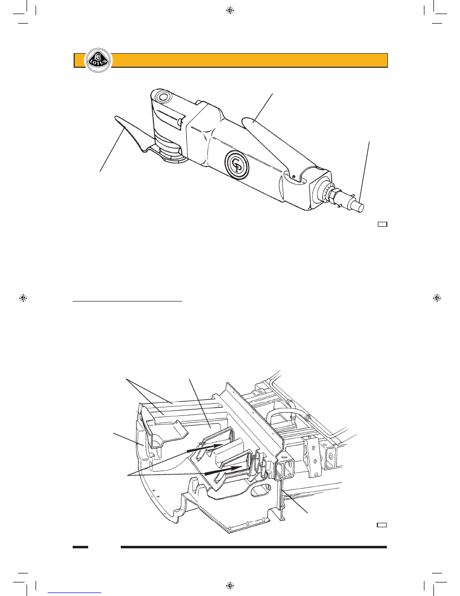
BQ.7 - FRONT CRASH STRUCTURE

The front crash structure consists of an upper and lower moulding bonded together and supplied only 

as an assembly.  It is bonded to the front face of the chassis, and is braced by an alloy undershield screwed 

to the bottom front edge of the chassis, and to each lower side of the crash structure.  The unit also acts as a 

ducting for the engine cooling radiator and a.c. condenser (if fitted) which are mounted horizontally on its top 

surface in a bolted-on composite radiator housing.  Longitudinal tubes formed in the construction are designed 

to produce a particular crush characteristic in order to control the rate of deceleration of the vehicle occupants 

in a frontal collision.


Operating handle


     Compressed air inlet

Vibrating cutting blade


                      bj46


Crush tubes 


Radiator aperture

Crash structure

Airflow to 

climate chamber

via cut outs 

in tubes


Chassis front face


                     p84a


sn_bq_cyclone.indd   10

03/03/2006   10:53:41

Page 11


Lotus Service Notes   


    Section BQ


To remove the crash structure:

Remove the front clamshell (see sub-section BR.5).

Remove the front undershield by releasing the three screws securing each lower side of the structure to 

the shield, and the three screws securing the shield to the front lower edge of the chassis.

Drain the coolant and remove the radiator and pipework (see section KH).

Remove the driving lamps (if fitted) from the crash structure, along with the towing strut, horn, alarm siren 

and wiring harness.

Use a seal cutting knife to cut the bond between the structure and the front face of the chassis. For access 

to some of the bonding areas, it may be necessary to cut away some parts of the structure, rendering the 

unit unsuitable for refitment. Take care not to damage the surface of the chassis when cutting the adhe-

sive.


It is not necessary to remove all traces of old adhesive from the chassis, but a uniform surface must be 

available for the new adhesive bead. The remaining adhesive must be securely bonded and be cut with 

a scalpal blade to leave an even thickness of 1 - 2 mm.


Prepare the new structure for bonding:

Dry fit the new structure to the chassis, and check that a good fit is achieved. Fettle the structure or remove 

old adhesive as necessary until the fit is satisfactory.

Re-activate the surface of the old adhesive on the chassis using Betawipe 4000 (see sub-section BQ.5), 

and clean and prime the bonding area on the new crash structure using Betaclean 3900 and Betaprime 

5404 (see sub-section BQ.5).


Bonding surface on chassis

Composite crash

structure


                   b278a

sn_bq_cyclone.indd   11

03/03/2006   10:53:41

Page 12


Lotus Service Notes   


    Section BQ


Apply a bead of Betaseal/mate adhesive (see sub-section BQ.5) to the bonding surface in the manner 

shown.

Fit the structure to the chassis and press into position to spread the adhesive. Use several clamps around 

the joint flange to retain the structure until the adhesive has cured; This will take approximately 4 hours 

dependent on atmospheric conditions, with a longer period required in dry atmospheres.

Fit the undershield, radiator (see sub-section KH.4), front clamshell (see sub-section BR.5) and remaining 

parts.

BQ.8 - WINDSCREEN FRAME

The windscreen frame is a single ICSRTM moulding with hollow, foam filled sections, and incorporates a 

forward extending buttress at each side to brace the frame against the front chassis.  A separate dash baffle 

panel is used to bridge the space between frame underside and chassis scuttle, and provide for the routing of 

climate control pipework and air ducting, and other services.

Application of  

adhesive bead

Betaseal bead


        b279


Windscreen frame


Dash baffle panel

Demist air duct

Face level

vent duct


Chassis scuttle

Heater pipe


                   b282b

sn_bq_cyclone.indd   12

03/03/2006   10:53:41

Page 13


Lotus Service Notes   


    Section BQ

The shape of the frame is critical to the windscreen fit, and structural repairs to the frame itself are not 

recommended.  It is not generally economic to attempt to remove the windscreen frame intact for refitment, 

as the elastomeric adhesive bonding the frame to the chassis requires cutting with a reciprocating knife, and 

access to the joints is sometimes obscured.  The recommended procedure is to cut the frame as necessary to 

allow its removal without damage to the dash baffle panel.  If the sills are to remain fitted, it will be necessary 

to carry out some minor work on the screen buttress to sill panel joint, where a panel overlap occurs.

To Replace Windscreen Frame

1.  Remove the front wheelarch liners and front clamshell (see sub-section BR.5), and for improved access, 

the two doors.

2.  Remove the windscreen (see sub-section BR.14).

3.  Remove the instrument binnacle and fascia top panel (see sub-section BR.13), and release the fixings 

between dash upper extrusion and screen frame.

4.  Release the brake hose/pipe connector at the front end of each buttress on the windscreen frame.  Release 

all harnesses and other components from the windscreen frame buttresses as necessary.

5.  Remove the wiper motor mechanism from the windscreen frame.

6.  Use a sealant cutting tool to cut the bond between the windscreen frame buttresses and chassis, and 

between the frame and 'B' posts, and between the frame underside and dash baffle panel.  Remove the 

windscreen frame.

7.  Cut the adhesive securing the drainage gutter around the front of the frame, to allow transfer to the new 

frame.

8.  If the dash baffle panel is to be replaced, the clutch pipe and climate control cables must be released and 

threaded through the panel before cutting the adhesive.

                              Primer band on chassis

                                                    Heater pipe grommet

                  Primer band on baffle


          Dash baffle panel

Foam strip


      b283b

sn_bq_cyclone.indd   13

03/03/2006   10:53:42


Content   ..  7  8  9  10   ..