Snowmobile Arctic Cat (2006 year). Instruction - part 18


  Index      Snowmobiles / ATV     Snowmobile Arctic Cat - instruction 2006 year


Search            


Content   ..  16  17  18  19   ..


Snowmobile Arctic Cat (2006 year). Instruction - part 18


68

MAINTENANCE

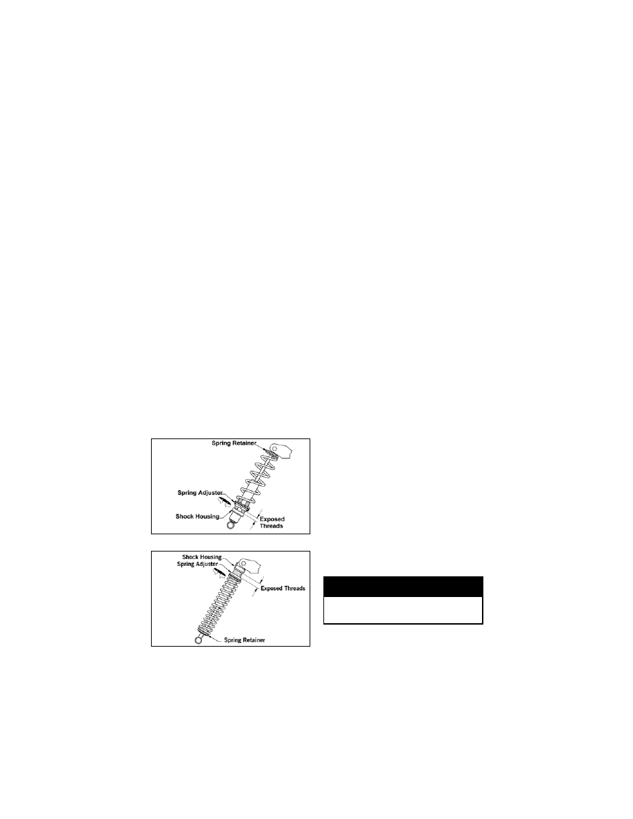
The front shock springs are individ-

ually adjustable for the terrain con-

ditions and driving style of the

operator. The spring adjuster has

been set at the factory so the correct

amount of threads are exposed

between the spring adjuster and the

shock housing as an initial setting.

Additional ski pressure can be

obtained by tightening the spring

t e n s i o n ;   s k i   p r e s s u r e   c a n   b e

decreased by relaxing spring ten-

sion.

  N OT E :   E q u a l   a d j u s t m e n t s

should be maintained on both
sides of the snowmobile.

To adjust spring tension, rotate the

entire spring in whichever direction

is desired. If after adjusting spring

tension you note the snowmobile

front end wants to pitch, relax the

spring tension on the side that is

pitching. If both sides are pitching,

relax the spring tension on both

sides.

 NOTE: The spring adjuster will

normally rotate with the spring.

734-501B

734-500B

Adjusting Front Shocks (Fox Air 
Shocks)

 NOTE: It is recommended to

monitor the air pressure in the air
shocks once every month.

 NOTE: Adjusting air shocks

may be done by the snowmobile
owner if qualified to do so. If the
owner does not feel qualified,
take the snowmobile to an autho-
r i z e d  A rc t i c   C a t   S n ow m o b i l e
dealer for this service. This ser-
v i c e   i s   a t   t h e   d i s c r e t i o n   a n d
e x p e n s e   o f   t h e   s n o w m o b i l e
owner.

The air shocks are individually

adjustable for the terrain conditions

and driving style of the operator.
The shocks are preset at 3.5 kg/cm

2

(50 psi) as an initial setting (4.2 kg/
cm

2

 (60 psi) on the M-7 LE); how-

ever, it is possible to “fine tune” the

shocks to match the operator ’s

weight, riding style, and terrain con-

ditions.

 NOTE: Care should be taken to

h a v e   e q u a l   p r e s s u r e   i n   t h e
s h o ck s   b e fo r e   o p e r a t i n g   t h e
snowmobile.

To increase or decrease air pressure,

use the following procedure.

 NOTE: When adjusting air pres-

sure, all weight must be removed
from the front suspension, and
the shock absorbers must be fully
extended.

 NOTE: Adding air pressure will

increase the air spring force;
r e d u c i n g   a i r   p r e s s u r e   w i l l
decrease air spring force.

1. Remove the air valve cap from

the shock.

! WARNING

Do not exceed 105 kg/cm

2

 (150

psi) in the shock.

MAINTENANCE

69

2. Thread the valve of Air Shock

Pump (p/n 2603-324) onto the

shock air valve approximately

six rotations.

 NOTE: As the pump is being

attached to the shock, the hose
will fill with air. This will result in a
lower gauge pressure 0.14-3.52
kg/cm

2

 (2-5 psi).

3. To decrease air pressure in the

shock, press the black bleed

valve button half way down and

hold until desired pressure is

attained.

 NOTE: Pressing the button fully

down and releasing it will allow
only a small amount of air to
escape (micro-adjust).

4. To increase air pressure in the

shock, pump until desired pres-

sure is attained.

5. Remove the pump valve from

the shock air valve.

 NOTE: As the pump valve is

being removed from the shock,
the sound of air loss is from the
pump hose, not from the shock.

6. Install the air valve cap onto the

shock.

Skid Frame Front Arm

 NOTE: On some models, the

front arm limiter straps are not
adjustable.

The skid frame front arm shock

spring and limiter straps are adjust-

able. However, Arctic Cat recom-

mends that the shock spring be

maintained as loose as possible.

Tightening the skid frame front arm

shock spring may cause improper

balance and may ruin the handling

features of the snowmobile.

The length adjustment of the front

arm limiter straps determines the

weight distribution between the

front of the skid frame and the skis.

Tightening the limiter strap (short-

ening the strap) will pull up on the

front of the skid frame and will

increase ski pressure. Loosening the

limiter strap (lengthening the strap)

lowers the front of the skid frame

and decreases ski pressure.
When customizing the amount of ski

pressure, be sure to adjust both

straps equally and do not over-adjust

the limiter straps to adversely affect

steering and operator control of the

snowmobile. Some experimentation

may be required until the proper

adjustment for the operator’s indi-

vidual style is obtained.

0730-537

0739-714

! WARNING

Do not adjust the front arm lim-
iter straps to a point at which
steering and operator control of
the snowmobile are adversely
affected.

70

MAINTENANCE

Adjusting Rear Spring Pre-Load

Proper adjustment of rear spring

pre-load is necessary to get the most

comfortable ride. The chart is

designed to help in setting up rear

spring pre-load; however, riding

style is the single greatest factor in

determining rear spring require-

ments.

NOTE: These cam position set-

tings are suggestions only. Personal
riding style will greatly influence
cam position settings. Spend time
to determine setting preferences.

Rear spring pre-load adjustment is

accomplished by rotating the adjust-

ing cams. Position 3 provides the

stiffest ride, and position 1 is for the

light driver or slow-speed trail

riding. Position 2 is for the average

operator under normal conditions.

Always rotate the cam from the

lighter position to the heavier posi-

tion.

727-720A

To rotate an adjusting cam, use the

spark plug wrench from the tool kit.

Rotate the wrench until the cam is in

the desired position. To stiffen the

ride, rotate the cam so as to raise the

spring end. Make the appropriate

adjustment on the other cam.

Articulating Skid Fame
(Bearcat Wide Track STD)

The rear articulating portion of the

skid frame has two adjusters which

control the amount of travel in the

rear suspension.
These two adjusters have been pre-

set at the factory and should require

no further adjustment.
If adjustment is ever required, rotate

the two adjusters equally to permit

12.5-25 mm (1/2-1 in.) travel of the

articulating portion of the suspen-

sion.

0739-642

Rider Weight (lb)

Cam Position

Up to 180 

1

180-240

2

Over 240

3

! CAUTION

Never force the adjustment cams
from the low position to the high
position. Cam damage may occur.

MAINTENANCE

71

Overload Springs 

Some models have overload springs

built into the rear suspension. When

either carrying a heavy load or

riding 2-up, the overload springs

should be engaged by rotating the

spring tension blocks to the UP posi-

tion. The spring tension blocks lock

in an over-center position when

engaged. To either engage or disen-

gage the spring tension blocks, use

the Spring Block Tool, a spark plug

socket, and a screwdriver to adjust

the spring block to the desired posi-

tion. Make sure both spring blocks

are in the same position (either

engaged or disengaged).

0739-625

LIGHTS

The correct taillight/brakelight bulb

is p/n 0109-460. The correct head-

light bulbs are p/n 0609-251 for the

high beam and p/n 0609-252 for the

low beam.

 NOTE: On the Crossfi re/ M-

Series models, the correct head-
light bulb for low beam is p/n
0609-693.

Removing and Installing 
Taillight/Brakelight Bulb

1. Remove the screws securing the

taillight/brakelight lens; then

remove the lens.

0728-239

0737-302

0739-712

2. Push in on the bulb and rotate it

counterclockwise to remove it

from the socket.

3. Install the new bulb in the

socket by pushing it in and

rotating it clockwise.

4. Install the lens and secure with

the screws.


Content   ..  16  17  18  19   ..