Snowmobile Arctic Cat (2002 year). Instruction - part 82
5-47
5
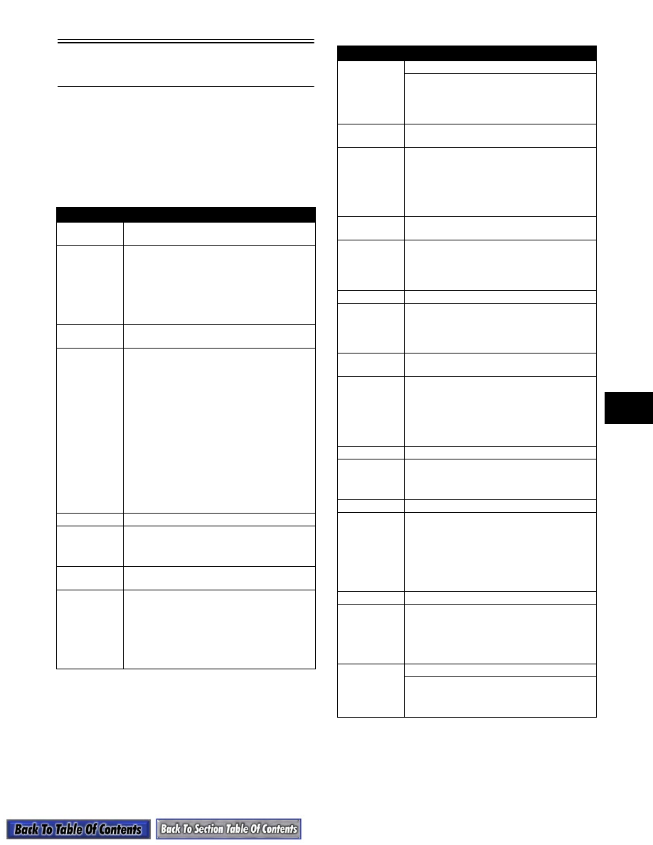
Wire Color Code and
Function Description
NOTE: The following wire color code and func-
tion description will assist in using the Main Har-
ness and Hood Harness wiring diagrams (see
Section 6). Note that some colors are numbered.
When a numbered color appears on either of the
wiring diagrams, refer to this color code descrip-
tion page, and it will provide you with additional
information.
COLOR
FUNCTION — DESCRIPTION
Brown
Electrical Common;
Chassis Ground
The brown wire is connected to the chassis
at the engine stator plate and also through
the voltage regulator chassis bolt (prior to
1989, the taillight harness also had a chassis
connection). The headlight bracket is
grounded on some models to reduce the
bracket RFI emissions. All brown wires are
common ground.
Yellow
AC Power; 13 Volts AC (Alternating
Current)
The yellow wire is connected to the engine
stator plate lighting coil and the voltage regu-
lator. The voltage produced by the lighting
coil is very engine RPM dependent. The volt-
age regulator is necessary to maintain 13.5
VAC on the yellow wire whenever the engine
exceeds about 3000 RPM. All yellow wires
are 13 VAC. The signal on the yellow wire is
AC. Not only is the voltage level of this signal
RPM dependent, but the signal frequency
(cycles per second) is RPM dependent as
well. The electric tachometer uses this
changing frequency phenomenon to indi-
cate the engine RPM. An electric tachometer
will operate properly when connected to any
yellow (13 VAC) and brown (common
ground) wire pair.
White
Headlight Low Beam
The white wire connects the dimmer switch
to the headlight bulb. The low beam filament
will illuminate when the dimmer switch con-
nects the white wire to 13 VAC power.
Blue
Headlight High Beam and Indicator
Light
The blue wire connects the dimmer switch to
the headlight bulb. The high beam will illumi-
nate when the dimmer switch connects the
blue wire to 13 VAC power. Some models
use a tachometer with a high beam indicator
light. The high beam indicator light will also
illuminate when the dimmer switch connects
the blue wire to 13 VAC power.
COLOR
FUNCTION — DESCRIPTION
Violet
Ignition System “Shut-Off”
The violet wire connects the ignition system
CDI module to the throttle control switches.
Ignition spark is interrupted when any of the
switches close, connecting the violet wire to
a common ground.
Red/White
#1
High Temperature Warning Light
Some models use a speedometer with a
high temperature warning light. The red/
white #1 wire connects the high temperature
sensor to the temperature warning light. The
“temp” light will illuminate when the sensor
connects the red/white #1 wire to common
ground.
Red/White
#2
Solenoid Coil Power
The red/white #2 wire connects the ignition
switch (12 volt DC) power to the solenoid.
The solenoid will activate when the ignition
switch connects the red/white #2 wire to the
+ 12 VDC battery power.
Red #1
Brakelight
The red #1 wire connects the brake control
assembly switch to the brakelight filament.
The brakelight will illuminate when the brake
switch connects the red #1 wire to 13 VAC
power.
Red #2
Electric Start Battery Power;
12 Volts DC (Direct Current)
The red #2 wire connects the battery positive
post (+12 VDC) to the ignition switch through
the fuse holder. All electric start red #2 wires
are +12 VDC. If the fuse “blows,” all red #2
wires are disconnected from the battery and
battery charging (via the charging diode) dis-
continues until the fuse is replaced.
Red #3
Low Oil Warning Light
The red #3 wire connects the low oil sensor
to the “oil” warning light. The “oil” light will
illuminate when the sensor connects the red
#3 wire to 13 VAC power.
Gray
Electric Fuel Level Gauge
Some models are equipped with an electric
fuel level gauge. The gray wire connects the
in-tank resistive sensor to the gauge. As the
fuel level rises, the sensor resistance
decreases, and the gauge needle rises; con-
versely, as the fuel level goes down, the sen-
sor resistance increases, and the gauge
needle drops.
Orange
Reverse Alarm
Some models are equipped with a reverse
gear and reverse alarm. The orange wire
connects the reverse switch to the reverse
alarm. The reverse alarm will “beep” when
the switch connects the orange wire to 13
VAC power.
Yellow/Red
and Red/
Yellow
DC Power Coil
Some models are equipped with a DC Power
Coil. The yellow/red and red/yellow wires
provide power to the Arctic Power Valve
(APV).