Snowmobile Polaris Two Stroke (2007 year). Instruction - part 72
11.25
BATTERY & ELECTRICAL SYSTEMS
11
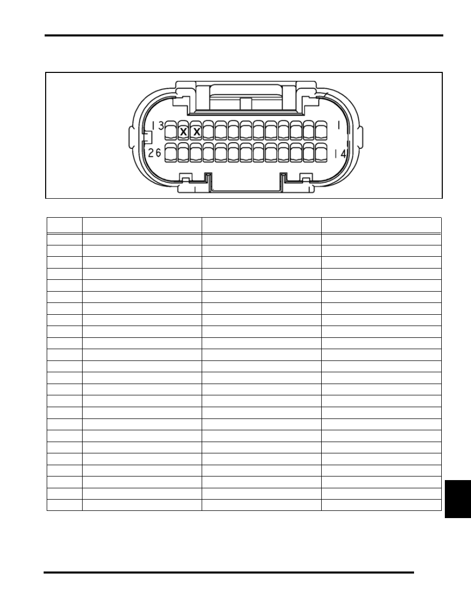
26 Pin CNB ECU Connector
NOTE: Wire Entry View
P
IN
C
OLOR
G
OES
T
O
C
ONNECTOR
F
UNCTION
1
ORANGE
PTO IGNITION COIL
COIL POWER
2
BLUE / YELLOW
STATOR - FUEL INJECTOR COIL
FUEL INJECTOR POWER COIL
3
BLUE / YELLOW
STATOR - FUEL INJECTOR COIL
FUEL INJECTOR POWER COIL
4
GREEN
STATOR - CRANK POSITION SENSOR
5 TOOTH COIL SIGNAL
5
WHITE
STATOR - CRANK POSITION SENSOR
2 TOOTH COIL SIGNAL
6
YELLOW
MAG FULL LOAD INJECTOR
INJECTOR CONTROL GROUND
7
YELLOW / WHITE
MAG PART LOAD INJECTOR
INJECTOR CONTROL GROUND
8
GREEN
PTO FULL LOAD INJECTOR
INJECTOR CONTROL GROUND
9
GREEN / WHITE
PTO PART LOAD INJECTOR
INJECTOR CONTROL GROUND
10
RED / WHITE
TPS
5 VDC POWER SUPPLY
13
WHITE / YELLOW
EV SOLENOID
SOLENOID CONTROL GROUND
14
BROWN
MAG IGNITION COIL / STATOR / STATOR
GROUND
15
GREEN / RED
STATOR - EXCITER COIL
EXCITER COIL
16
GREEN / YELLOW
STATOR - EXCITER COIL
EXCITER COIL
17
WHITE / GREEN
CRANK POSITION SENSOR
5 TOOTH COIL GROUND
18
WHITE / RED
CRANK POSITION SENSOR
2 TOOTH COIL GROUND
19
BLACK / BLUE
DETONATION SENSOR
GROUND
20
PURPLE
DETONATION SENSOR
SENSOR SIGNAL
21
RED / BLUE
MAG / PTO FULL LOAD INJECTOR
INJECTOR POWER SUPPLY
22
RED / BLUE
MAG / PTO PART LOAD INJECTOR
INJECTOR POWER SUPPLY
23
AQUA
TPS SENSOR
SIGNAL
RETURN
24
BLACK / BLUE
COOLANT TEMP. SENSOR / TPS
SENSOR GROUND
25
YELLOW
COOLANT TEMP. SENSOR
SENSOR SIGNAL RETURN
26
RED
EV SOLENOID
REGULATED VOLTAGE