Snowmobile Polaris Two Stroke (2007 year). Instruction - part 71


  Index      Snowmobiles / ATV     Snowmobile Polaris Two Stroke - instruction 2007 year


Search            


Content   ..  69  70  71  72   ..


Snowmobile Polaris Two Stroke (2007 year). Instruction - part 71


11.21

BATTERY & ELECTRICAL SYSTEMS

11

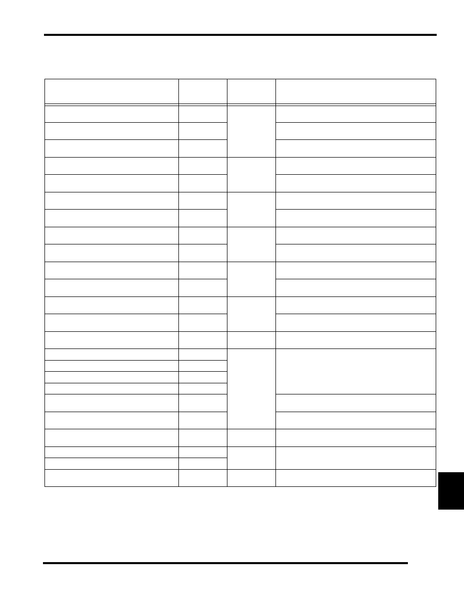
Diagnostic Trouble Codes (DTCs)

2007 CFI Diagnostic Trouble Codes

T

ROUBLE

 C

ODE

P-C

ODE

MFD B

LINK


C

ODE

D

ESCRIPTION

Throttle Position Sensor Unrealistic Transition

P0120

1

TPS signal changes too rapidly to be correct. Can be caused by faulty 
connections or a faulty TPS.

Throttle Position Sensor Voltage High

P0123

TPS signal is above 4.39 Vdc. Can be caused by a faulty wire 
connection or faulty TPS.

Throttle Position Sensor Voltage Low

P0122

TPS signal is below 0.7 Vdc. Can be caused by a faulty wire 
connection or faulty TPS.

Engine Coolant Temperature Sensor Voltage High

P0118

2

Sensor signal is above 4.8 Vdc. Can be caused by a faulty wire 
connection or faulty temperature sensor.

Engine Coolant Temperature Sensor Voltage Low

P0117

Sensor signal is below 0.1 Vdc. Can be caused by a faulty wire 
connection or faulty temperature sensor.

Intake Air Temperature Circuit Voltage High

P0113

3

Sensor signal is above 4.9 Vdc. Can be caused by a faulty wire 
connection or faulty TBAP.

Intake Air Temperature Circuit Voltage Low

P0112

Sensor signal is below 0.19 Vdc. Can be caused by a faulty wire 
connection or faulty TBAP.

Barometric Pressure Sensor Voltage High

P0108

4

Sensor signal is above 3.23 Vdc. Can be caused by a faulty wire 
connection or faulty TBAP.

Barometric Pressure Sensor Voltage Low

P0107

Sensor signal is below 1.25 Vdc. Can be caused by a faulty wire 
connection of faulty TBAP.

Exhaust Temperature Sensor Circuit Voltage High

P0546

5

Sensor signal is above 4.9 Vdc for at least 2 minutes and the engine 
has been running at or above 3000 RPM.

Exhaust Temperature Sensor Circuit Voltage Low

P0545

Sensor signal is below 0.06 Vdc for at least 2 minutes and the engine 
has been running at or above 3000 RPM.

Detonation Sensor Circuit Voltage High

P0328

6

Engine speed is above 6000 RPM and the sensor signal is above 4.3 
Vdc for at least 2 seconds.

Detonation Sensor Circuit Voltage Low

P0327

Engine speed is above 6000 RPM and the sensor signal is below 1.23 
Vdc for at least 2 seconds.

Exhaust Valve Solenoid Circuit Malfunction

P1477

8

Solenoid control circuit is OPEN. Can be caused by faulty wiring, 
solenoid, or ECU.

MAG Part Load Injector Circuit Open

P0261

7

OPEN circuit or short to ground. Can be caused by faulty wiring, 
injector, stator or ECU.

MAG Full Load Injector Circuit Open

P1261

PTO Part Load Injector Circuit Open

P0264

PTO Full Load Injector Circuit Open

P1264

Fuel Injector Voltage Too High

P2148

Engine is running, but the injector voltage is above the acceptable 
limit. Can be caused by faulty wiring, ECU or stator.

Fuel Injector Voltage Too Low

P2147

Engine is running, but the injector voltage is below the acceptable 
limit. Can be caused by faulty wiring, ECU or stator.

Vehicle Speed Sensor No Signal

P0500

Steady LED

Sensor has given a speed that is not possible with given engine 
conditions. Can be caused by a faulty sensor, wiring or ECU.

MAG Ignition Coil Circuit Malfunction

P0351

9

Failure within the primary circuit. Can be caused by faulty wiring, 
ignition coil, or ECU.

PTO Ignition Coil Circuit Malfunction

P0352

5 Tooth CPS Signal Missing

P0335

10

Engine is running, but there is no signal from the 5 tooth CPS. Can 
be caused by a faulty stator, wiring or ECU.

11.22

BATTERY & ELECTRICAL SYSTEMS

MFD Blink Codes

The check engine LED will display a blink code whenever the
ECU determines there is a problem with one or more of the
sensors. Use Digital Wrench to troubleshoot, fix and clear the
codes.

When a blink code is displayed, the CHECK ENGINE light will
illuminate for 1/2 second “on” and 1/2 second “off” with a 1
second “off” interval between close.

DTC Troubleshooting

Always use the Digital Wrench diagnostic software program to
troubleshoot DTCs, MFD blink codes, and overall performance
problems.

Digital Wrench can be used to display trouble codes and offers
guided diagnostics. Guided diagnostics allows the technician to
perform diagnostic checks in an attempt to isolate the root
problem.

1.

To access trouble codes, click on the “!” button. If any
codes are listed, select a code to proceed.

2.

To access guided diagnostics, click on the “SPECIAL
TESTS” (toolbox) button. Then click “DIAGNOSTIC
PROCEDURES”.

3.

Select a code or system in the ‘SYSTEM CHARTS” menu.
A description of the DTC or system will be displayed.

4.

Click on (A) to activate guided diagnostics.

5.

Click on (B) to view a wiring schematic of the component
or system.

6.

Click on “X” to exit the current screen.

5 Tooth CPS Signal Intermittent

P0336

Steady LED

Engine is running, but the pulses from the 5 tooth CPS are incorrect. 
Can be caused by a faulty stator, wiring harness or ECU.

5 VDC Sensor Supply Voltage Low

P0643

Sensor supply voltage is below an acceptable limit. Can be caused 
by faulty wiring or ECU.

Chassis Voltage High

P0563

System voltage is too high. Can be caused by faulty wiring or 
regulator / rectifier.

Chassis Voltage Low

P0562

System voltage is too low. Can be caused by a faulty wiring or 
regulator rectifier.

Ignition Voltage Circuit Malfunction

P0350

Engine is running but a problem is found with the ignition coil power 
circuit. Can be caused by faulty wiring or ECU.

2 Tooth CPS Signal Missing

P0385

Engine is running and there is a signal from the 5 tooth CPS, but not 
the 2 tooth CPS sensor. Can be caused by faulty wiring, stator or 
ECU.

Chassis Relay Coil Open Circuit

P1611

The chassis relay control circuit is open. Can be caused by faulty 
wiring or a faulty relay.

2007 CFI Diagnostic Trouble Codes

T

ROUBLE

 C

ODE

P-C

ODE

MFD B

LINK


C

ODE

D

ESCRIPTION

(A) (B)

11.23

BATTERY & ELECTRICAL SYSTEMS

11

CFI Clutch Guard Electrical Center

COVER / SPARE BELT HOLDER

IGNITION COILS

CAPACITOR

REGULATOR / RECTIFIER

ECU

COIL MOUNT

GUARD PLATE

6 Ft.Lbs. (10 Nm)

6 Ft.Lbs. (10 Nm)

6 Ft.Lbs. (10 Nm)

6 Ft.Lbs. (10 Nm)

11.24

BATTERY & ELECTRICAL SYSTEMS

34 Pin CNA ECU Connector

NOTE:  Wire Entry View

P

IN


C

OLOR

G

OES

 T

O

 C

ONNECTOR

F

UNCTION

3

RED/BLUE

SPLICE

K LINE POWER

4

ORANGE

ECU POWER

EXTERNAL POWER

5

WHITE/BLACK

EXHAUST TEMP. SENSOR

SIGNAL

6

BLUE

TBAP

AIR TEMP SIGNAL

7

GREEN/BLUE

IGNITION SWITCH

STARTER LOCKOUT

8

RED/WHITE

TBAP

5 VDC POWER SUPPLY

9

GREEN/RED

GROUND SPEED SENSOR SPLICE

SPEED SIGNAL

10

RED/BLACK

ELECTRIC START

BATTERY VOLTAGE

11

WHITE/BLUE

CHASSIS RELAY

COIL GROUND

12

RED/BLACK

THROTTLE FLIPPER SAFETY SWITCH

SOFTWARE BASED IGNITION KILL SIGNAL

13

BROWN

ECU GROUND SPLICE

ECU GROUND

14

RED/BLUE

CHASSIS / HOOD #2

WATER TEMP. SIGNAL

16

YELLOW/RED

CHASSIS / HOOD #1

TACHOMETER SIGNAL

17

ORANGE

REGULATOR / RECTIFIER

VOLTAGE BOOST POWER

21

PINK

DIAGNOSTIC

K-LINE

22

GRAY

GRAY SPLICE

MODE SELECT

23

WHITE

CHASSIS/HOOD #1

PERC LED

24

GREEN

TBAP

PRESSURE SENSOR SIGNAL

25

BLUE/WHITE

CHASSIS / HOOD #1

OVERHEAT / DET LED

26

ORANGE/GREEN

ELECTRIC START

CHARGE RELAY COIL GROUND

27

BLACK/WHITE

DIAGNOSTIC SPLICE - CHASSIS / HOOD #1

DIAGNOSTICS / CHECK ENGINE LED

29

BLACK

TETHER / IGN. SWITCH / SAFETY SLAP 
SWITCH

HARDWARE STOP - IGNITION KILL SIGNAL

30

BLACK/BLUE

SENSOR GROUND SPLICE #1

SENSOR GROUND

31

GRAY

LH CONTROL

PERC SIGNAL

32

RED

REGULATOR POWER SPLICE

REGULATED POWER

33

ORANGE

REGULATOR / RECTIFIER

VOLTAGE BOOST POWER

34

ORANGE

REGULATOR / RECTIFIER

VOLTAGE BOOST POWER


Content   ..  69  70  71  72   ..