Snowmobile Polaris Two Stroke (2007 year). Instruction - part 42


  Index      Snowmobiles / ATV     Snowmobile Polaris Two Stroke - instruction 2007 year


Search            


Content   ..  40  41  42  43   ..


Snowmobile Polaris Two Stroke (2007 year). Instruction - part 42


6.19

CLUTCHING

6

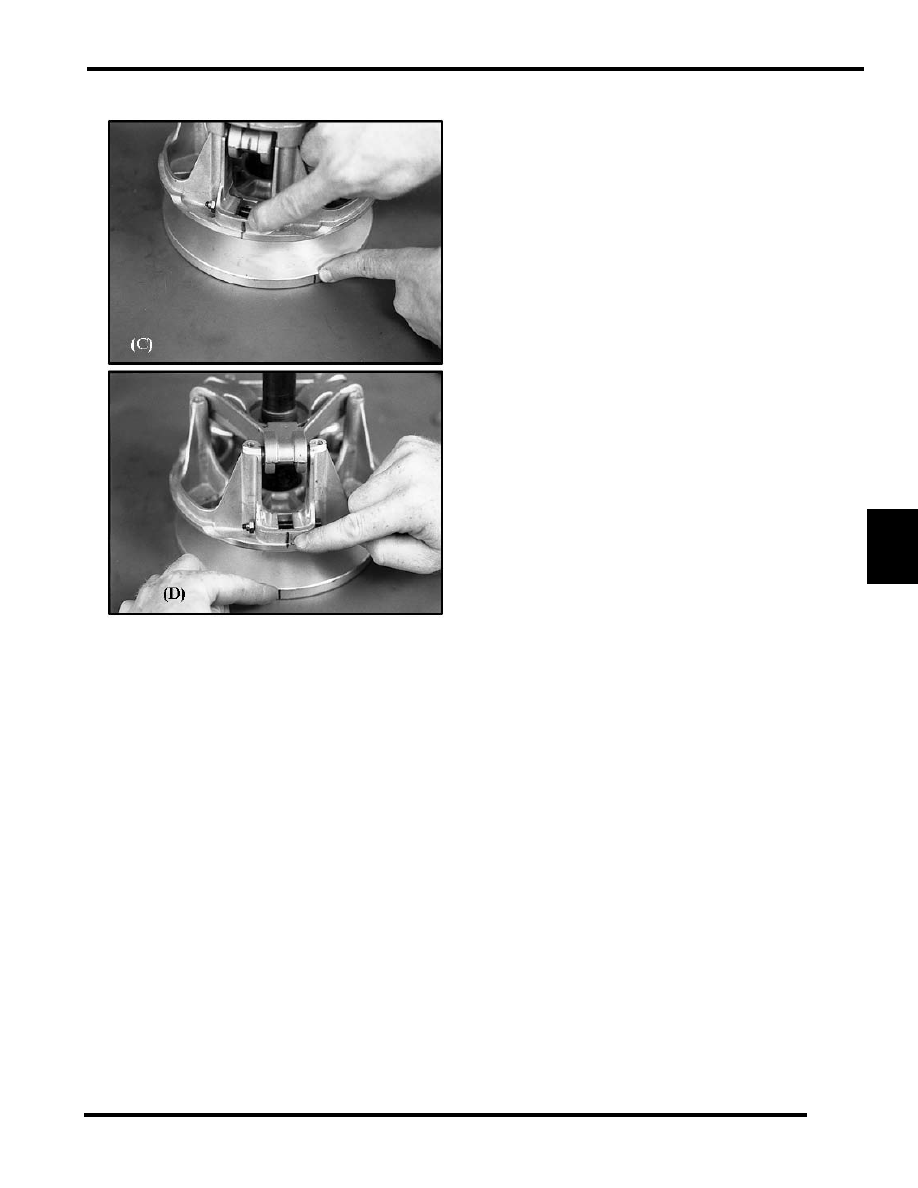
Vary the amount and thickness of spacer washers (washer
thickness may vary slightly). Re-index marked spider leg to
another tower. This can be done because spider has little effect
on overall clutch balance. 

Re-indexing the spider 1/3 turn clockwise, or 1 leg, will allow
the realignment of the moveable and stationary sheaves as
previously marked (D). For EXAMPLE: 0.020" or 0.032" (0.5
- 0.8mm) washer removed - re-index spider clockwise 1/3 turn.

NOTE: Alignment marks on the sheaves should be
with in 1" (25.4mm) after final assembly and
torquing.

6.20

CLUTCHING

Drive Clutch Installation

NOTE:  Always clean the clutch taper before re-installing clutch on engine.

1.

Place a clutch taper reamer (PN 2870576) in a vise (A) and lubricate the cutting edges with cutting oil. Clean the clutch taper
by manually rotating the clutch clockwise on the reamer one or two revolutions. Only use the weight of the clutch and do not
push down on the clutch while turning. This will clean up any galling or scoring of the bore taper.

2.

Check crankshaft taper for galling or scoring. If necessary clean the taper evenly with 200 grit emery cloth (B).

3.

The clutch taper and the crankshaft taper should be clean and dry. Do not use harsh cleaners which may cause clutch taper to
corrode, or damage the crank seal.

4.

Clean clutch taper with lacquer thinner or isopropyl alcohol (C).

5.

Slide clutch onto crankshaft taper (D).

6.

Install the retaining bolt with all spacers and washers or o-rings (E) that were on the bolt when it was removed.

7.

Hold the clutch with the holding wrench (F) PN 931417-A. Re-check torque after first operation or test ride.

8.

Torque retaining bolt to specification.

9.

Run engine then re-torque the retaining bolt to specification.

Drive Clutch Bolt Torque

ENGINE

BOLT

TORQUE

Fuji

7/16-20

40-45 ft-lb (55-

62N-m)

Liberty 440/500/600/

700 carbureted

14mm

50 ft-lb (68N-m)

Liberty 600/700 CFI

14mm

80 ft-lb (108N-m)

CAUTION

Re-torque the drive clutch bolt after running the engine 

for several minutes.

6.21

CLUTCHING

6

DRIVEN CLUTCH

Components

Driven Clutch Removal

1.

Remove the drive belt.

2.

Apply and lock the parking brake.

3.

Remove the driven clutch bolt and washers (A).

NOTE:  Count the number and location of the spacer
washers located on the fastener and behind the
clutch.

4.

Slide the driven clutch off the jackshaft.

5.

Inspect the splines and replace jackshaft if damage is found.

Driven Clutch Installation

1.

Install the driven clutch bolt with the same amount of
washers at removal.

2.

Torque the bolt to specification.

3.

Check for correct belt deflection.

Driven Clutch Disassembly

1.

Helix Removal:

• Remove the fasteners securing the helix to the 

moveable sheave.

• Using a flat-blade screwdriver, carefully pry the helix 

up and out of the sheave.

2.

Install the clutch into the clutch compression tool, PN
8700220. Use the clutch compression extensions, PN PS-
45909.

HELIX

SNAP RING

SPRING

SPRING CUP

MOVEABLE SHEEVE

DEFLECTION SPACER

STATIONARY SHEEVE

BELT DEFLECTION SCREW

ROLLER ASSEMBLY

(Team LW Clutch Shown)

T 

Helix Fasteners = 60 - 80 In.Lbs. (7 - 9 Nm)

Driven Clutch Retaining Fastener = 17 Ft.Lbs. (23 Nm)

A

6.22

CLUTCHING

3.

Compress the roller assembly to access the snap ring. Lock
the clutch compression tool chain to hold the roller
assembly down.

4.

Carefully remove the snap ring.

5.

Slowly release the compression tool.

6.

Disassemble the clutch components. Replace damaged or
worn components.

Driven Clutch Assembly

1.

Clean the components with clutch cleaner. Reassemble the
clutch components. Reference the illustration for order of
assembly.

2.

Visually align the wide notch on shaft with the wide
opening on the roller assembly. Place the roller assembly
on the spring.

3.

While keeping the roller assembly centered on the shaft,
compress the roller assembly and spring down into the
moveable sheave enough to expose the snap ring groove.

4.

Install the snap ring, then release the compression tool.

5.

On dual-angled Team helixes, locate the desired angles
etched on the helix cover. Install the helix so that the desired
ramps fit around the two rollers. Push the helix down into
the sheave, while keeping the fastener holes aligned.

6.

Torque the helix fasteners to specification.

Belt to Sheave Clearance Inspection

The distance between the belt and the moveable sheave on the
drive clutch is very important. This distance controls the starting
ratio (lowers starting ratio is most preferable) and the position
of the clutch weight to engine RPM.

The distance between the belt and movable sheave should be as
close to .020" (.5 mm) as possible with out creating drag on the
belt when positioned around the hub at the bottom of the
sheaves. 

1.

Force the belt (1) to the stationary sheave (toward engine)
of the drive clutch.

NOTE:  Measure total belt to sheave clearance with a
new belt installed.

2.

Install a feeler gage between the belt and moveable sheave

3.

Distance should be .005" - .035" (.1 - .9 mm)

Belt to Sheave Clearance Adjustment

Belt to Sheave clearance can be adjusted in two ways:

1.

Try several new belts to achieve proper clearance.

2.

You can add or remove shims from under the spider to
increase or decrease the belt to sheave clearance. See
“Spider Indexing” on page 6.18.

NOTE: Belts with various widths will affect belt
deflection since they will fit differently in the driven
clutch. See “Belt Deflection Inspection” on
page 6.23.

WARNING

Wear eye protection when removing and installing the 

roller assembly.

In. / mm. 

Belt to Sheave Clearance: .005" - .035" (.1 - .9 mm)

1

2


Content   ..  40  41  42  43   ..