Snowmobile Polaris Two Stroke (2007 year). Instruction - part 28


  Index      Snowmobiles / ATV     Snowmobile Polaris Two Stroke - instruction 2007 year


Search            


Content   ..  26  27  28  29   ..


Snowmobile Polaris Two Stroke (2007 year). Instruction - part 28


5.5

ENGINE

5

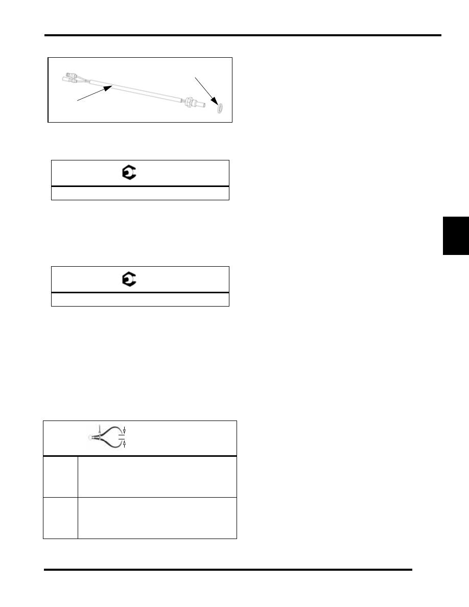
Water Temperature Sensor Replacement

1.

Remove the sensor (1) from the cylinder head.

2.

Replace the washer (2) and torque the sensor to
specification.

Engine Mount Replacement

1.

Use the correct Engine Mount Socket (PN PS-45384 or
2871989).

2.

Replace the old motor mount if necessary with new and
torque new motor mount to specification.

Cylinder Stud Installation

If you are replacing the crankcase on the 500, 600 HO, 600 CFI
or 700 CFI Liberty engines, the new cases will come with the
cylinder studs not installed, you will need to assemble the
cylinder studs to a determined length.

You will need to thread in the Dri-Lok treated portion of the stud
into the case to a determined length below. After stud assembly
remove the Dri-Lok residue from the case assembly before
assembly.

T 

Temperature Sensor: 18 ft-lb (24 N-m)

T 

28 ft.lb (37.9 N-m)

In. / mm. 

600 CFI
700 CFI

Long Studs Height (Exhaust side) = 4.13" 

(105mm)

Small Stud Height (Intake side) = 2.16" 

(55mm)

500/600 

HO

Long Studs Height (Exhaust side) = 3.66" 

(93mm)

Small Stud Height (Intake side) = 2.16" 

(55mm)

1

2

5.6

ENGINE

500/600/700 Water/Oil Pump Cross Shaft 

Disassembly

NOTE: Inspect all parts for wear or damage during
disassembly. Replace all seals, o-rings, and gaskets
with Genuine Pure Polaris parts during assembly.
Refer General chapter for general inspection
procedures.

1.

Remove the oil pump (1).

2.

Carefully pull out the brass bushing (2) and o-ring (3).

3.

Remove the water cover fasteners.

4.

Remove the cover and gasket.

5.

Remove the impeller nut (11). 

6.

Remove the impeller (10) and flat washer (9).

7.

Remove the mechanical seal (8).

8.

Pry out the seal (7) that is behind the mechanical seal. 

9.

Press out the water pump shaft (5) out toward the oil pump
side.

10. Remove the thrust washers from the cross shaft (4, 6).

500/600/700 Water/Oil Pump Cross Shaft 

Assembly

1.

Install the seal (7) so that the spring side is facing the
intake side of the case and press it in so that it is bottomed
out in the case.

2.

Install the mechanical seal (8) into the case with the sealant
facing the intake side of the engine. Use the Seal
Installation Tool PN 2872010.

IMPORTANT: It is very critical to use the Installation

tool PN 2872010 to set the operating height of the

mechanical seal. Failure to do so will cause seal to

leak.

3.

Install the thrust washers (4, 6) on to the cross shaft.

4.

Install the O-ring (3) on the cross shaft.

5.

Install the flanged pump bearing (2) onto the cross shaft.

6.

Install oil pump (1) onto the crankcase and torque the bolts
to 84 in-lb (31 N-m).

7.

Place the impeller washer (9), impeller (10) and impeller
nut (13) onto the other side of the cross shaft.

8.

Torque the impeller nut (13) to 120 in-lb (14 N-m).

1

2

3

4

5

6

7

8

9

10

11

120 in-lb

Sealant

Case side

Cover side

 (14 N-m)

84 in-lb

(10 N-m)

T 

Oil Pump Fasteners: 84 in-lb (10 N-m)

T 

Impeller Nut: 120 in-lb (14 N-m)

5.7

ENGINE

5

Cylinder Head / Head Components

Cylinder Head Disassembly

1.

Remove enough engine coolant so that no coolant remains
in the cylinder head. 

2.

Remove the airbox, electrical, and ignition components
from the cylinder head.

3.

Remove the cooling hoses from the thermostat and throttle
body circuit fittings.

4.

Evenly loosen the cylinder head screws. Always clean the
screw threads as they are removed.

NOTE: The thermostat cover screws only require
removal when access to the thermostat is desired.

5.

Lift the head cover and cylinder head assembly up and off
of the cylinders.

6.

Discard original o-rings. Never re-use o-rings.

7.

If engine coolant spilled into the cylinder(s), wipe each
cylinder dry with a clean shop rag or paper towel. If unsure
how much coolant spilled into cylinders and crankcase,
locate the two crankcase drain screws located on the front,
lower crankcase halve. 600/700 CFI drains are located on
the bottom of the crankcase and the engine would have to
be removed.

8.

Remove each screw to allow the coolant to drain out of the
engine.

Cylinder Head Assembly

1.

Cylinder head assembly is the reverse of disassembly with
the addition of these notes:

• Always use new o-rings.

• Inspect the cylinder bores, combustion chamber domes, 

piston faces and head cooling passages for damage or 
foreign material. Resolve any issues prior to re-
assembly.

• Follow the cylinder head torque specifications and 

torque sequence illustrations found at beginning of 
chapter.

Recoil/Stator Removal

1.

Remove the recoil cover bolts (1).

2.

Remove the recoil assembly (2).

Temperature Sensor

O Rings

Knock Sensor

O Rings

Head Cover

O Ring

Thermostat

Spark Plugs

Bleed Screw

1

2

3

4

5

6

7

8

9

10

90 ft-lb

(16 N-m)

(122 N-m)

12 ft-lb

48 in-lb
(5 N-m)

(12 N-m)

9 ft-lb
(12 N-m)

9 ft-lb

5.8

ENGINE

3.

Remove the recoil basket bolts (3).

4.

Remove the recoil basket (4).

5.

Using a strap wrench PN PU-45419 hold the flywheel (6) while taking the flywheel nut (5) off.

6.

Using the Flywheel Puller PN 2871043, thread the puller bolts into the flywheel. Do not install puller bolts more than 5/16"
(7mm) into flywheel threads or stator damage may result. 

7.

Tighten the center bolt and remove the flywheel (6).

8.

Note the ignition timing marks that match up with the stator to the crankcase or scribe additional marks for reference for
assembly.

9.

Remove the stator bolts (7)

10. Remove the pulse coil fasteners (8).

11. Remove the pulse coils (9) and stator (10). Be careful when removing the wires of the stator.

Recoil/Stator Assembly

NOTE:  Inspect all parts for wear or damage during disassembly. Replace all seals, o-rings, and gaskets with
Genuine Pure Polaris parts during assembly. Refer General chapter for general inspection procedures.

1.

Install the stator (10) and the pulse coils (9).

2.

Install the pulse coil fasteners into the case and torque to specification.

3.

Install the stator bolts (7) and torque to specification.

4.

Install the flywheel (6) so that it matches up with the index of the woodruff key.

5.

Apply Loctite 242 to the threads of the flywheel nut (5) and onto the end of the crankshaft.

6.

Holding the flywheel with the strap wrench, torque the flywheel nut to 90 ft-lb (122 N-m).

7.

Install the recoil basket (4) and the recoil basket bolts (3) on the flywheel and torque the bolts to 9 ft-lb (12 N-m).

8.

Install recoil assembly (2) and torque to 9 ft-lb (12N-m).

T 

Pulse Coil Fasteners: 48 in-lb (5 N-m)

T 

Stator Fasteners: 12 ft-lb (16 N-m)

T 

Flywheel Nut: 90 ft-lb (122 N-m)


Content   ..  26  27  28  29   ..