Snowmobile Polaris Two Stroke (2007 year). Instruction - part 25
4.17
FUEL DELIVERY
4
CLEANFIRE INJECTION (CFI)
Injector Replacement
The Cleanfire system utilizes 3 different color injectors. If you
are replacing an injector you must replace it with the same color
injector you remove.
The color is indicated in three ways, 1) it will be on the short wire
harness that is attached to the injector, 2) the injector will have
a colored dot on the shaft of the injector 3)it is indicated on the
label of the ECU.
If the color injector is not available you may replace all injectors
with a different color and you must program the ECU to run the
new installed color.
If it is verified that an injector needs to be replaced, you must
first find out what injector color is on the unit. You can do this
by checking the decal that is located on the top portion of the
ECU or by the color band that is next to the injector on the
harness.
1.
Bleed the fuel rail. See “Fuel Rail Bleeding” on page 4.20.
2.
Remove the seat and fuel tank. See “IQ Fuel Tank
Removal” on page 10.6.
3.
If removal of the engine is needed. See “600/700 CFI
Engine Removal” on page 5.29.
4.
Replace the injectors.
5.
Install engine. See “600/700 CFI Engine Installation” on
page 5.35.
6.
Re-flash ECU with Digital Wrench.
7.
Test run.
600/700 CFI Injector Replacement
If an injector is suspect to failure please use the following
procedure to replace injector(s) on the
CFI
engine.
Using Digital Wrench, identify which injector needs to be
replaced.
NOTE: If the injector is on the upper fuel rail, only
the air box needs to be removed to gain access to
the failed injector.
NOTE: If the injector is on the lower fuel rail, engine
removal is necessary for injector access. See “600 /
700 HO CFI ENGINE” on page 5.29.
600/700 CFI Fuel Rail/Injector(s) Removal/
Installation
NOTE: When installing replacement injector(s) keep
the red protective cap on the end of the injector to
prevent damage when installed. Follow the steps
and remove when instructed to do so.
1.
Depressurize the fuel rail. See “Fuel Rail Bleeding” on
page 4.20.
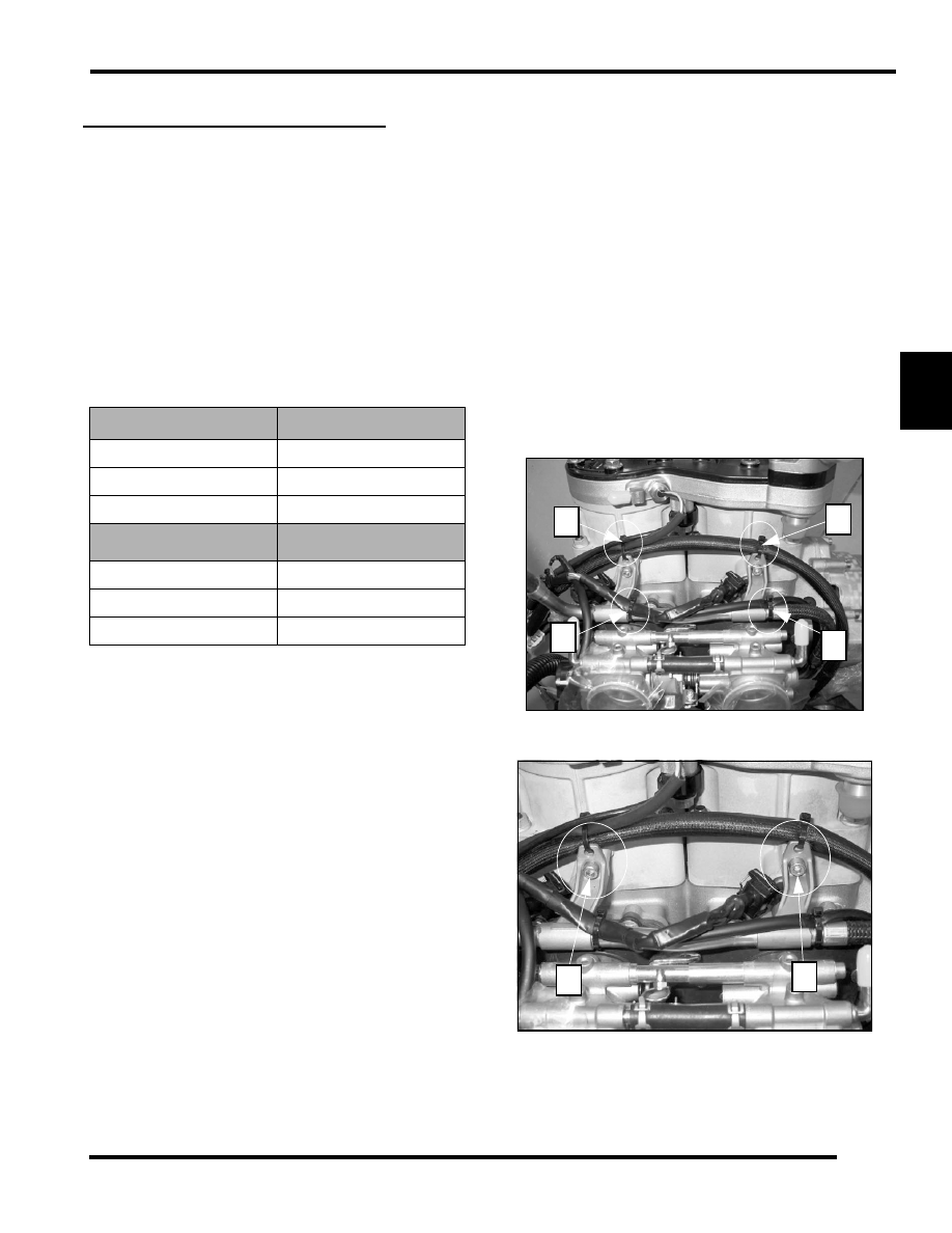
2.
Remove the panduit straps (1-4) as shown.
3.
Remove the fuel rail by taking out the two hex bolts (5,6)
holding it to the engine.
INJECTOR
COLOR
1202853-053
Yellow
1202853-027
Blue
1202853-015
Red
INJECTOR
KITS
COLOR
2203325-053
Yellow
2203325-027
Blue
2203325-015
Red
1
4
3
2
6
5