Snowmobile Polaris DEEP SNOW (2005 year). Instruction - part 64


  Index      Snowmobiles / ATV     Snowmobile Polaris DEEP SNOW (TRAIL RMK, 600 RMK, 700 RMK, 800 RMK, 900 RMK, 600 SWITCHBACK, 800 SWITCHBACK) - instruction 2005 year


Search            copyright infringement  


Content   ..  62  63  64  65   ..


Snowmobile Polaris DEEP SNOW (2005 year). Instruction - part 64


ELECTRICAL

13.13

Headlight Bulb Filament Continuity Test

1. Turn the Multitester dial to the ohms (Ω) position.
2. Disconnect the wire harness from the headlight bulb.
3. Viewing the back of the bulb with the terminal blades at the 9, 12 and 3 o’clock position, connect the black multitester

lead to the 9 o’clock blade.

4. Touch the red tester lead to the 12 o’clock terminal and then to the 3 o’clock terminal, noting the resistance value of

each. A reading of between 2 and 5 ohms is good. An open reading indicates a bad element.

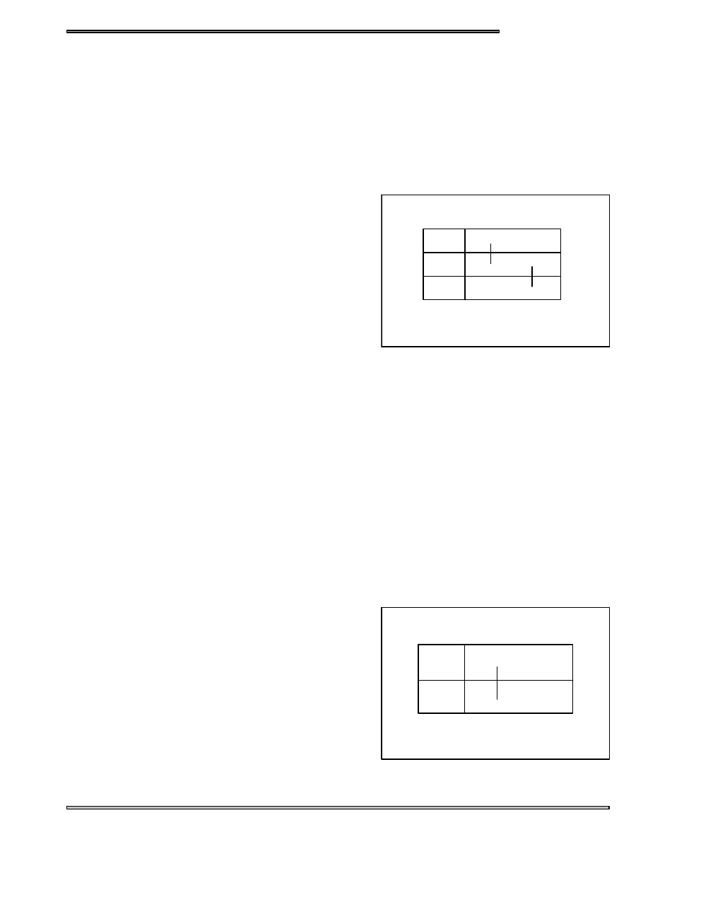
Hi/Lo Beam Switch Testing

1. Set the multitester dial to the ohms (Ω) position.
2. If the Hi/Lo switch has not been removed from the machine,

disconnect the switch to harness plug-in connector.

3. With the Hi/Lo switch in the Lo beam position, check the

resistance between the yellow and the green switch wires.

The reading should be less than .4 ohms.

4. Turn the Hi/Lo switch to the Hi beam position and the

multitester should indicate an open circuit (OL) reading.

5. Move one of the tester leads from the green to the red switch

wire. The multitester should now read less than .4 ohms.

6. Turn the Hi/Lo Switch back to the Lo beam position and the

meter should again read an open circuit (OL).

Seat Harness Troubleshooting

1. Remove the taillight lens.
2. Remove the two taillight bulbs and the brakelight bulb.
3. Separate the seat harness from the main harness by unplugging the connector at the right rear of the tank.
4. With the multitester dial set on ohms (Ω) connect either meter test lead to the brown seat harness wire.
5. Touch the other tester lead to first the yellow wire and then the orange wire. Observe the readings. Readings other

than an open circuit (O.L.) indicate a shorted harness or bulb socket.

NOTE: The bulb socket tangs sometimes short to ground with the bulb removed.

6. Check between the yellow and orange wires in the same manner to check for a short between the brake and running

lights. If damaged wiring is found, remove the seat.

7. Tip the seat over and remove the right side seat cover staples. Locate and repair the harness problem.
8. Reinstall the staples and re-check the seat harness.

Ignition Switch Testing (Non-Electric Start)

1. Set the multitester dial to the ohms (Ω) position. Connect one

of the tester leads to either of the switch terminals and the other

tester lead to the other switch terminal.

2. With the switch off, the reading should be less than .4 ohms.

With the switch on, the reading must be an open circuit (OL).

3. Check the resistance between each of the switch terminals

and the switch body. With the switch still in the on position,

there must be an open circuit (OL) reading. Readings other

than those listed indicate a defective switch.

Low

High

Grn

Yel

Yel/Rd

High/Low Switch

D

D

D

D

Blk

Brn

Off

On

Ignition Switch

D

D

ELECTRICAL

13.14

Ignition Switch Testing (Electric Start Models)

NOTE: Refer to the appropriate model and year wiring diagram for

ignition switch wire colors and connections.

1. Disconnect wires. Set the multitester dial to the ohms (Ω)

position.

2. With the key in the off position, check the resistance between

the G (Ground, brown) terminal and the M (Mag, black)

terminal. This reading must be less than .4 ohms.

3. Turn the key to the on position. The multitester should now

read an open circuit (OL).

4. Move the tester lead from the G terminal to the switch housing

and re-check the reading. It should also be an open circuit

(OL).

5. Place one of the tester leads on the B (Battery, red) terminal

and the other tester lead on the S (Starter, blue) terminal. With

the key in the on position, there must be an open circuit (OL) reading.

6. Turn the key to the start position. The reading should be less than .4 ohms. Readings other than the ones listed

indicate a defective switch.

500/600/700/800 Temp Light

Models with TPS are fitted with a thermistor sensor. This sensor outputs a variable resistance with temperature. This allows more
capability for control when the over heat indicator light illuminates. Higher throttle positions require lower temperature for the
light to come on, possibly leading the operator to believe it to be a blinking light.

For example, the TEMP light will come on at idle (under 2000 RPM, 0% throttle) if coolant temperature reaches 230_F (110_C).
Timing retard initiates at 176_F if the TPS input is over 80--100%. For more severe conditions, the engine fail--safe is turned on
at high TPS input and high temperatures

At room temperature 68_ F (20_ C) the thermistor should read 2189 to 2675 Ω.

See chart below for other temperature resistances.

CAUTION:

If attempting to heat the sensor, heat only in a water bath. Never subject the sensor to an open flame to attempt to close the contacts
as sensor damage may result.

TEMP _F (_C)

Ω RESISTANCE RANGE

68 (20)

2189 -- 2675

149 (65)

455 -- 556

203 (95)

197 -- 240

239 (115)

120 -- 147

275 (135)

77 -- 94

Brn

Blk

R

R/W

Off

On

Start

D

D

D

D

Ignition Switch - Electric Start

ELECTRICAL

13.15

A

B

Off Idle Switch

Idle Switch

Plungers

Outward

Throttle Control

Cutaway

Engine Ground

Ignition Primary

Auxiliary Kill

Switch Contacts

Insulator

Conductor

The speed control assurance consists of two series connected switches. If one or both switch plungers are positioned

inward, the circuit is open and the engine will run.

At idle, with the throttle lever properly adjusted, the bottom switch circuit is open and the plunger is inward. The top

switch circuit is closed, and the plunger is outward. The speed control circuit is open, allowing the engine to run.

As the throttle lever is actuated to an off idle position, the top switch circuit is opened (plunger in) and the bottom switch

circuit is closed (plunger out). The speed control circuit is still open, allowing the engine to run.

In the event the carburetor or controls malfunction and allow the throttle cable to become slack, the circuit will close

(both switch plungers out), grounding the ignition system and causing the engine to stop.

Speed Control Assurance Adjustment

Throttle lever free play must always provide a specified clearance

between throttle lever and throttle block. This clearance is con-

trolled by the throttle cable sleeve(s) and the idle speed screw(s).

If the idle speed screw(s) is adjusted inward and the cable

sleeve(s) is not adjusted to take up the throttle lever to throttle

block clearance, the engine may misfire or kill upon initial throttle

opening.

CAUTION:

After any idle speed adjustments are made, the throttle lever to throttle block clearance and oil pump adjustment must

be checked and adjusted.

NOTE:

When adjustments are made on models which have more than one carburetor, refer to Section 6, Carburetion,

for proper carburetor synchronization adjustments.

Throttle Lever Freeplay -

.010 - .030″ (.25 - .8 mm)

.010-.030″ (.25-.8 mm)

ELECTRICAL

13.16

Speed Control Assurance Replacement

Auxiliary shut-off and speed control assurance switches are connected and replaced as a unit from the back side of

the throttle block.

1. Remove the handlebar pad and/or throttle block backing plate.

2. Slide out the auxiliary shut-off portion of the switch.

3. Remove the two screws securing the two speed control assurance switches.

4. Remove the switches noting their placement in the throttle block.

5. Replace the assembly and check its operation.

Auxiliary Shut--Off Switch Testing

1. Set the multitester in the ohms (Ω) position.

2. Disconnect the switch harness from the main wire harness.

3. Connect the two multitester leads to the two switch wires.

Test 1 - Open Circuit - Run

With the auxiliary shut-off switch in the ON position, the multitester should read an open circuit (OL). As the throttle

lever is moved from idle to off idle, the tester should continue to read an open circuit. If the tester fluctuates and the

throttle lever to throttle block clearance is adjusted properly, the switch assembly must be replaced.

Test 2 - Closed Circuit - Kill

The two speed control switches must make a complete circuit to kill the engine. To check the switches, pull the throttle

lever out away from the throttle block. With the switch plungers outward and the auxiliary shut-off switch in the ON

position, the multitester must read less than .4 ohms resistance. Inspect wires and repair if damaged, or replace switch

assembly.

Test 3 - Auxiliary Shut-Off

The multitester should read less than .4 ohms in the OFF position and an open circuit in the the ON position. Inspect

wires and repair if damaged, or replace switch assembly.

EDGE Fuel Sender Testing

Use the multitester ohmmeter to test the resistance of the fuel

sender.

Position

Ohms

Range

Empty

95 Ω

90 - 97.5 Ω

Full

7 Ω

4.5 - 13 Ω

The supply voltage to the gauge should be 13.5 VAC.

+

_

Fuel Gauge

Diode

Fuse

(0.2A)

Pur/Wh

Brn

Yel


Content   ..  62  63  64  65   ..