Suzki Burgman AN400. Manual - part 78
8-34 ELECTRICAL SYSTEM
BATTERY
SPECIFICATIONS
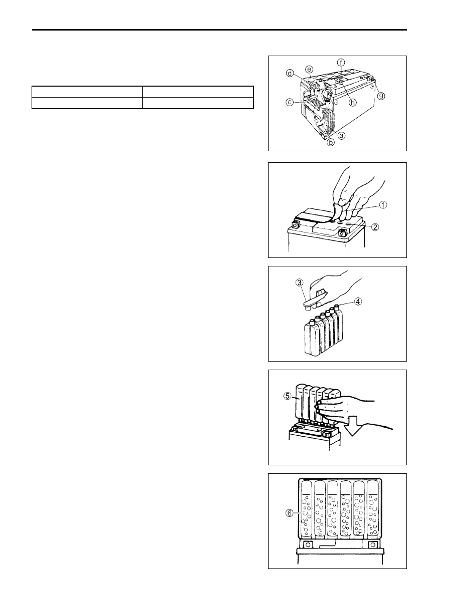
a
Anode plates
e
Stopper
b
Separator (fiberglass plate)
f
Filter
c
Cathode plates
g
Terminal
d
Upper cover breather
h
Safety valve
INITIAL CHARGING
FILLING ELECTROLYTE
• Remove the aluminum tape
1
sealing the battery electrolyte
filler holes
2
.
• Remove the caps
3
.
NOTE:
* After filling the electrolyte completely, use the removed caps
3
as the sealed caps of battery filler holes.
* Do not remove or pierce the sealed areas
4
of the electrolyte
container.
• Insert the nozzles of the electrolyte container
5
into the bat-
tery’s electrolyte filler holes, holding the container firmly so
that it does not fall. Take precaution not to allow any of the
fluid to spill.
• Make sure air bubbles
6
are coming up each electrolyte con-
tainer, and leave in this position for about more than 20 min-
utes.
Type designation
FT12A-BS
Capacity
12 V, 36 kC (10 Ah)/10 HR