Suzki Burgman AN400. Manual - part 76


  Index      Motorcycles     Suzki Burgman AN400 - service and repair manual 2002 year


Search            


Content   ..  74  75  76  77   ..


Suzki Burgman AN400. Manual - part 76


8-26     ELECTRICAL SYSTEM
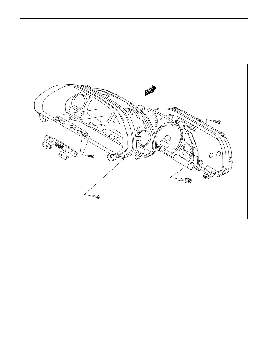
COMBINATION METER

REMOVAL AND DISASSEMBLY

• Remove the front meter panel. (

!

7-13)

• Disassembly the combination meter, as shown.

ELECTRICAL SYSTEM     8-27

INSPECTION

WATER TEMPERATURE GAUGE INSPECTION

• For the inspection procedure. (

!

6-9)

• Remove the frame cover. (

!

7-18)

• Disconnect the water temperature sensor coupler.
• With the ignition switch turned on and a variable resister con-

nected between the Dark green and Black/Brown lead wires
for the water temperature gauge needle indication when the
resistance is adjusted to the specified values.
If the indication excessively deviates from the standard value,
replace the meter with a new one.

PEEDOMETER INSPECTION
If the speedometer, odometer or trip meter does not function
properly, inspect the speedometer sensor and connection of
coupler. If the speedometer sensor and connection are all right,
replace the meter with a new one.

SPEED SENSOR INSPECTION

• Disconnect the speed sensor coupler.
• Connect 12 V battery, 10 k

 resistance and the tester to the

speed sensor lead coupler as shown.

#

09900-25008: Multi-circuit tester set

'

Tester knob indication: Voltage (

%

)

• Lift and turn the front wheel and check that voltage varies

between 0 – 12 V.

• If any abnormal condition is noted, replace the sensor with a

new one.

Water temperature gauge needle indication

Resistance 

Approx. 770 

Approx. 155 

Approx. 75 

Needle position


1


2


3

O/R

12V

B/W

P

10k

8-28     ELECTRICAL SYSTEM

FUEL LEVEL METER INSPECTION

• Remove the side leg shield. (

!

7-15)

• Disconnect the fuel pump coupler 


1

.

• Check that the fuel level meter moves properly when the

resistor is connected between the fuel pump coupler termi-
nals.

• If the indication excessively deviators from the standard

value, replace the meter with a new one.

NOTE:
* Prior to this inspection, check that the fuel gauge is functioning

properly.

* When reading the meter indication, wait at least for 20 sec-

onds after the resistor has been connected.

FUEL LEVELGAUGE INSPECTION
For the inspection procedure. (

!

5-11)

Resistor

Meter indication

Approx. 95 


1

Approx. 51 


2

Approx. 10 


3

ELECTRICAL SYSTEM     8-29

LAMP

HEADLIGHT

"

HEADLIGHT BULB REPLACEMENT

• Disconnect the lead wire couplers.
• Remove the headlight socket cover.
• Remove the headlight bulb 


1

 by releasing the bulb spring 


2

.

• Install the headlight in the revers order of removal.

HEADLIGHT BEAM ADJUSUMENT

• Adjust the headlight beam, both vertical and horizontal.


A

 Vertical adjuster (using a screw driver 


+

)


B

 Horizontal adjuster (using a screw driver 


+

If you touch the bulb with your bare hands, clean the bulb with a cloth  moistened with alcohol
or soapy water to prevent premature bulb failure.

E-03, 28,33

E-02, 19, 54


Content   ..  74  75  76  77   ..