Suzki Burgman AN400. Manual - part 66


  Index      Motorcycles     Suzki Burgman AN400 - service and repair manual 2002 year


Search            


Content   ..  64  65  66  67   ..


Suzki Burgman AN400. Manual - part 66


CHASSIS     7-67

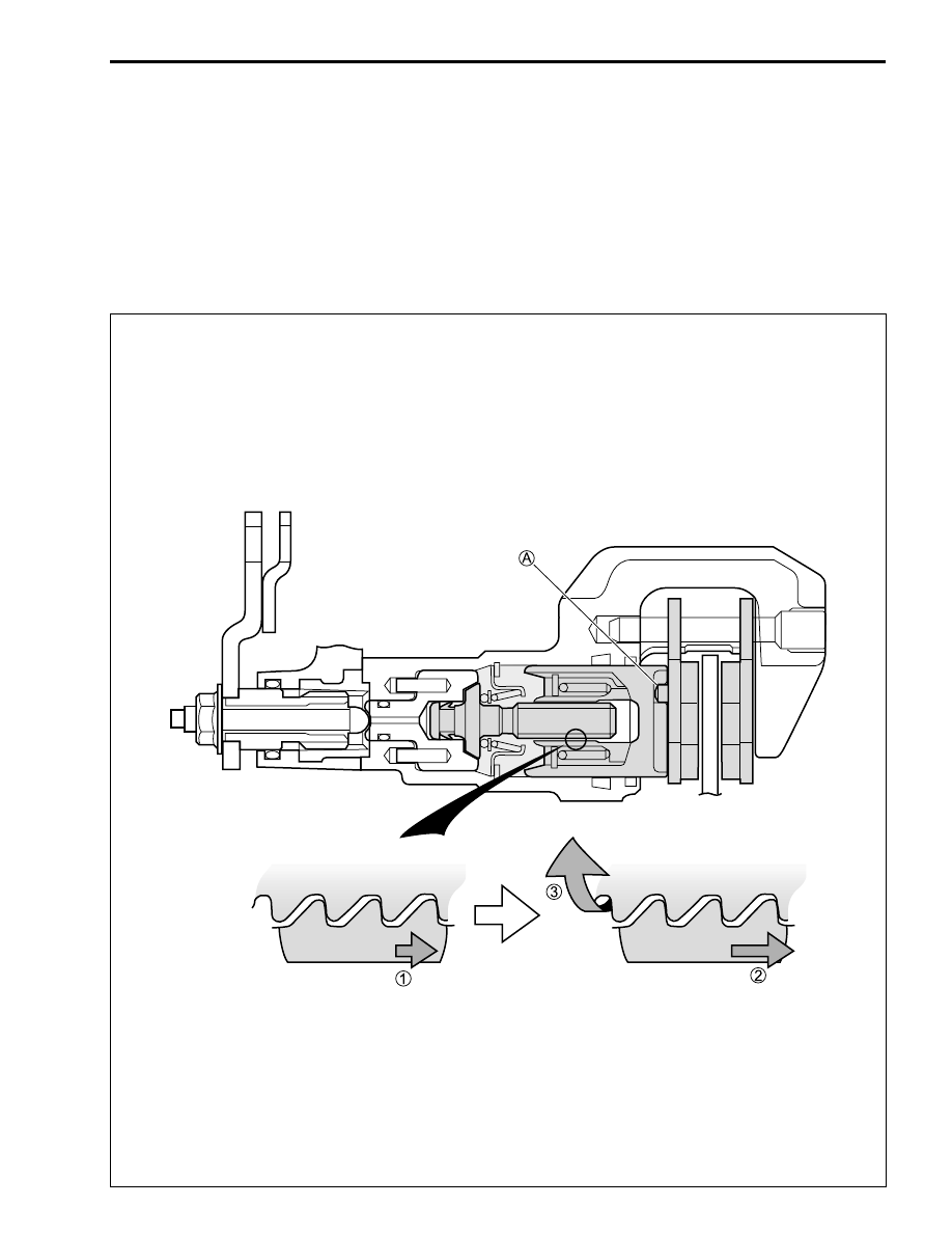
OPERATION (Brake pads are worn

Braking

Automatic adjuster operate)

If braking when the brake pad being worn, the caliper piston/adjust nut move [


1

] untill the clearance

depended on abrasion is done away.
The axial movement [


2

] is converted to rotary movement and acts on the adjust bolt and adjust nut. Only

the adjust bolt turns [


3

] because the caliper piston/adjust nut is fixed to the brake pad with caliper piston

groove and pad boss at 


A

. Thus, the adjust bolt keeps original position with rotating as well as the caliper

piston/adjust nut moves outside.
The adjust bolt stops rotating once the brake pad-to-disc clearance become zero, so the automatic adjuster
operation is completed.

7-68     CHASSIS

OVER-ADJUST PREVENTION MECHANISM
When rapid braking [


1

], the automatic brake-lock adjuster operation works too fast [


2

].

The caliper piston/adjust nut is forced to stop [


3

] as soon as the brake pad contacts with brake disk, but the

adjust bolt turns by inertia force [


4

] after that. The adjust bolt stops after the adjust bolt/nut clearance

becomes zero. On this account, the caliper piston/adjust nut can not return back [


5

] using the elasticity

transform of piston seal when releasing the brake lever. It is the over-adjust condition.

The spring is equipped between the caliper piston and the adjust nut for preventing the over-adjust, serves
damper interm of rapid caliper piston movement.
The spring compress [


2

] as soon as the caliper piston moves exponentially [


1

], the adjust nut moves [


3

],

[


4

] behind time. Here with, it is possible to make correct clearance of the adjust bolt/nut because the inertia

force with rapid movement does not work the adjust bolt.

Caliper piston

Piston seal

Hydraulic pressure

2

Rapid rotation

Adjust bolt

Adjust nut

1

Rapid braking

4

Turn by inertia

5

Impossible to return

3

Sudden stop

Spring

2

Spring compresses

1

Rapid braking

3

Spring tensions/

    Adjust nut moves

4

Rotate

CHASSIS     7-69

REAR SUSPENSION

REMOVAL AND DISASSEMBLY

• Remove the under cover 


1

. (

!

7-14)

• Remove the side leg shield. (

!

7-15)

• Remove the frame cover. (

!

7-18)

• Remove the trunk box. (

!

7-18)

• Remove the rear shock absorber adjuster 


2

.

1

  Cushion lever

2

  Rear shock absorber

3

  Spacer

4

  Bearing

A

  Rear shock absorber bolt

B

  Cushion lever mounting nut

C

  Rear cushion rod nut

D

  Rear shock absorber adjuster bolt

ITEM

    N·m

       kgf-m          Ib-ft

A

   50

       5.0           36.0

B

   78

       7.8           56.5

C

   50

       5.0           36.0

D

   10

       1.0             7.0

7-70     CHASSIS

• Disconnect the clamps.

• Remove the rear shock absorber bolt 


3

, cushion lever

mounting nut 


4

 and rear cushion rod nut 


5

.

• Remove the cushion lever nuts 


6


7

 and disassemble the

rear suspension linkage.

• Remove the cushion lever bearings using the special tools.

%

09930-30104: Sliding shaft
09923-73210: Bearing remover

INSPECTION

CUSHION LEVER

• Inspect the cushion lever body for crack, break or other

abnormal condition.

• Attempt to move the spacer laterally to see that no play exists.

Also, check the spacer for smooth turning.

• If any abnormal condition is noted in the spacer movement,

replace the bearing.


Content   ..  64  65  66  67   ..