Suzki Burgman AN400. Manual - part 64


  Index      Motorcycles     Suzki Burgman AN400 - service and repair manual 2002 year


Search            


Content   ..  62  63  64  65   ..


Suzki Burgman AN400. Manual - part 64


CHASSIS     7-59

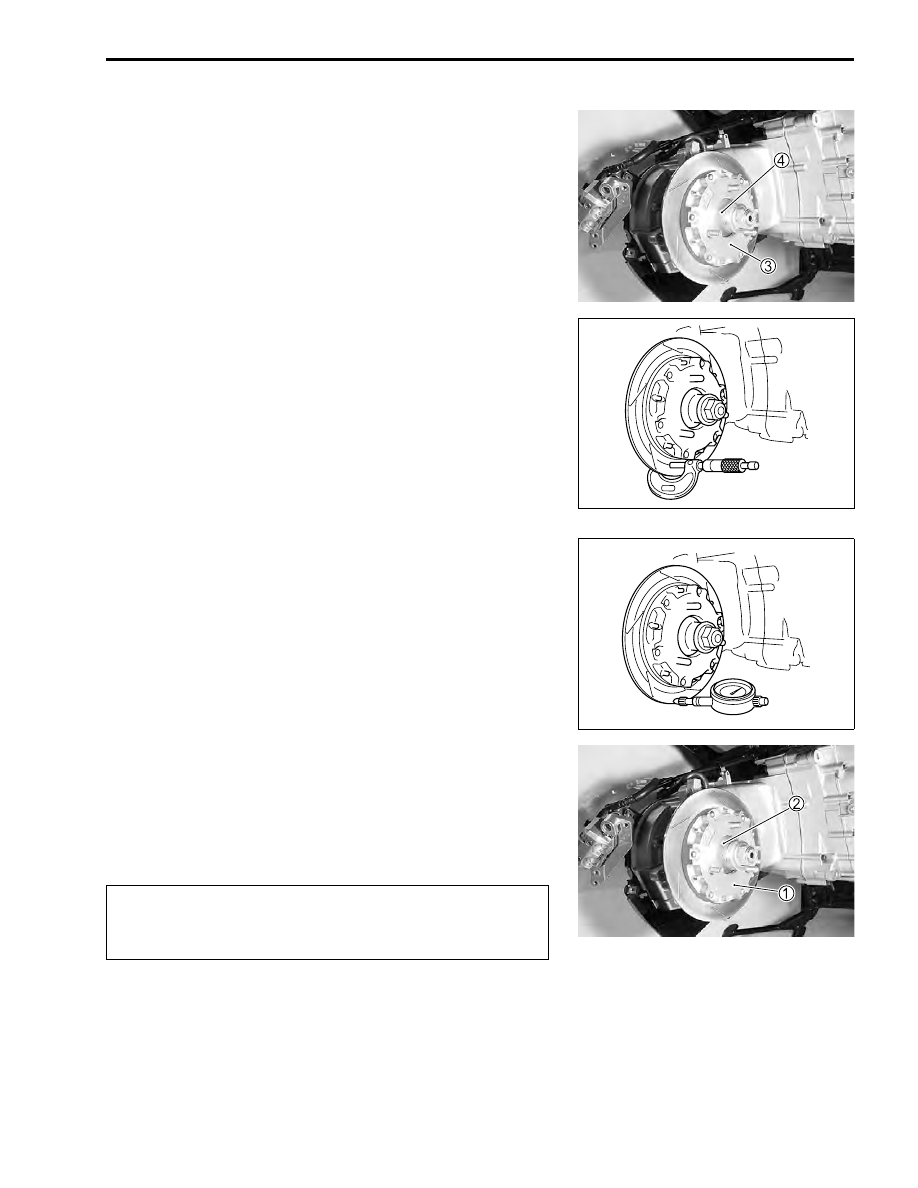
• Remove the brake disc 


3

 from the rear hub 


4

.

BRAKE DISC INSPECTION

• Check the brake disc surface for scratch, crack or abnormal

wear.

• Measure the disc thickness at several positions using a

micrometer.

• If the measurement is less than the service limit or any abnor-

mal condition is noted, replace the disc with a new one.

&

Brake disc thickness: Service Limit: 4.5 mm (0.18 in)

%

09900-20205: Micrometer (0 – 25 mm)

• Secure the brake disc by fitting an appropriate nut to the

wheel bolt.

• Measure the runout with a dial gauge.
• Replace the disc if the runout exceeds the service limit.

&

Brake disc runout: Service Limit: 0.30 mm (0.012 in)

%

09900-20607: Dial gauge (1/100 mm)
09900-20701: Magnetic stand

BRAKE DISC REASSEMBLY

• Reassemble the brake disc in the reverse order of removal.
• Pay attention to the following points:
• Install the brake disk 


1

 to the rear hub 


2

.

• Tighten the caliper mounting bolts to the specified torque.

$

#

Caliper mounting bolt: 25 N·m (2.5 kgf-m, 18.0 lb-ft)

When tightening the caliper mounting bolts, make
sure that the brake disc is slid on the rear hub all the
way to the end.

7-60     CHASSIS

MASTER CYLINDER REMOVAL AND DISAS-
SEMBLY

• Remove the handle cover. (

!

7-11)

• Remove the rear view mirror 


1

.

• Drain brake fluid from the combination brake reservoir. 

(

!

2-18)

• Disconnect the brake light switch lead wires.

• Remove the union bolt 


2

.

$

• Remove the master cylinder 


3

.

• Remove the brake light switch 


4

 and brake lever 


5

.

• Remove the boot 


6

 and remove the snap ring 


7

.

• Remove the piston/cup set 


8

 and spring 


9

.

Place a rag under the union bolt so that brake fluid
may not contact the parts.

CHASSIS     7-61

MASTER CYLINDER INSPECTION

• Wash clean the inside of master cylinder and the reservoir

tank with fresh brake fluid.

*

Specification and classification: DOT 4

• Inspect the cylinder wall, piston/cup set and spring for

scratch, corrosion or other damages.

• If any abnormal condition is noted, replace the inner parts or

master cylinder.

MASTER CYLINDER REASSEMBLY AND 
REMOUNTING

• Reassemble and remount the master cylinder in the reverse

order of removal and dissassembly.

• Pay attention to the following points:

$

• Install the master cylinder 


1

. (

!

7-31)

• Tighten the upper bolt first temporarily to provide clearance

on the lower side and then tighten both the bolts to the speci-
fication.

#

Master cylinder bolt: 10 N·m (1.0 kgf-m, 7.0 lb-ft)

• Install the brake hose and tighten the union bolt to the speci-

fied torque. (

!

9-23)

#

Union bolt: 23 N·m (2.3 kgf-m, 16.5 lb-ft)


2

 Master cylinder bolt


3

 Handlebars


4

 Master cylinder


5

 Punch mark


6

 Clearance

• Fill the system with brake fluid and bleed air. (

!

2-20)

• Perform the following inspections after the master cylinder

assembly has been completed.

* Brake  (

!

2-16)

* Wash each component with fresh brake fluid before

reassembly. Do not wipe off brake fluid after washing
the components.

* Replace the cup set (piston, primary cup, secondary

cup and spring) with a new one with brake fluid
applied.

7-62     CHASSIS

DELAY VALVE REMOVAL

• Drain brake fluid from the combination brake system. 

(

!

2-18)

• Remove the front leg shield. (

!

7-12)

• Remove the union bolts 


1

 and 


2

.

• Remove the brake pipe joint bolt 


3

.

• Remove the delay valve mounting bolts 


4

.

DELAY VALVE REMOUNTING

• Remount the delay valve in the reverse order of removal.
• Pay attention to the following points:
• Tighten the delay valve mounting bolt 


1

 together with the

clamp.

#

Delay valve mounting bolt: 10 N·m (1.0 kgf-m, 7.0 lb-ft)

• With the brake hose end contacted to the stopper, tighten the

union bolt to the specified torque.

#

Union bolt: 23 N·m (2.3 kgf-m, 16.5 lb-ft)

• Tighten the brake pipe joint bolt 


2

 to the specified torque.

#

Brake pipe joint bolt: 16 N·m (1.6 kgf-m, 11.5 lb-ft)

BRAKE-LOCK CABLE REPLACEMENT

• Remove the front box. (

!

7-14)

• Loosen the lock nut 


1

 of the brake-lock lever assembly 


2

.

• Remove the brake-lock cable 


3

.


Content   ..  62  63  64  65   ..