Suzki Burgman AN400. Manual - part 56


  Index      Motorcycles     Suzki Burgman AN400 - service and repair manual 2002 year


Search            


Content   ..  54  55  56  57   ..


Suzki Burgman AN400. Manual - part 56


CHASSIS     7-27

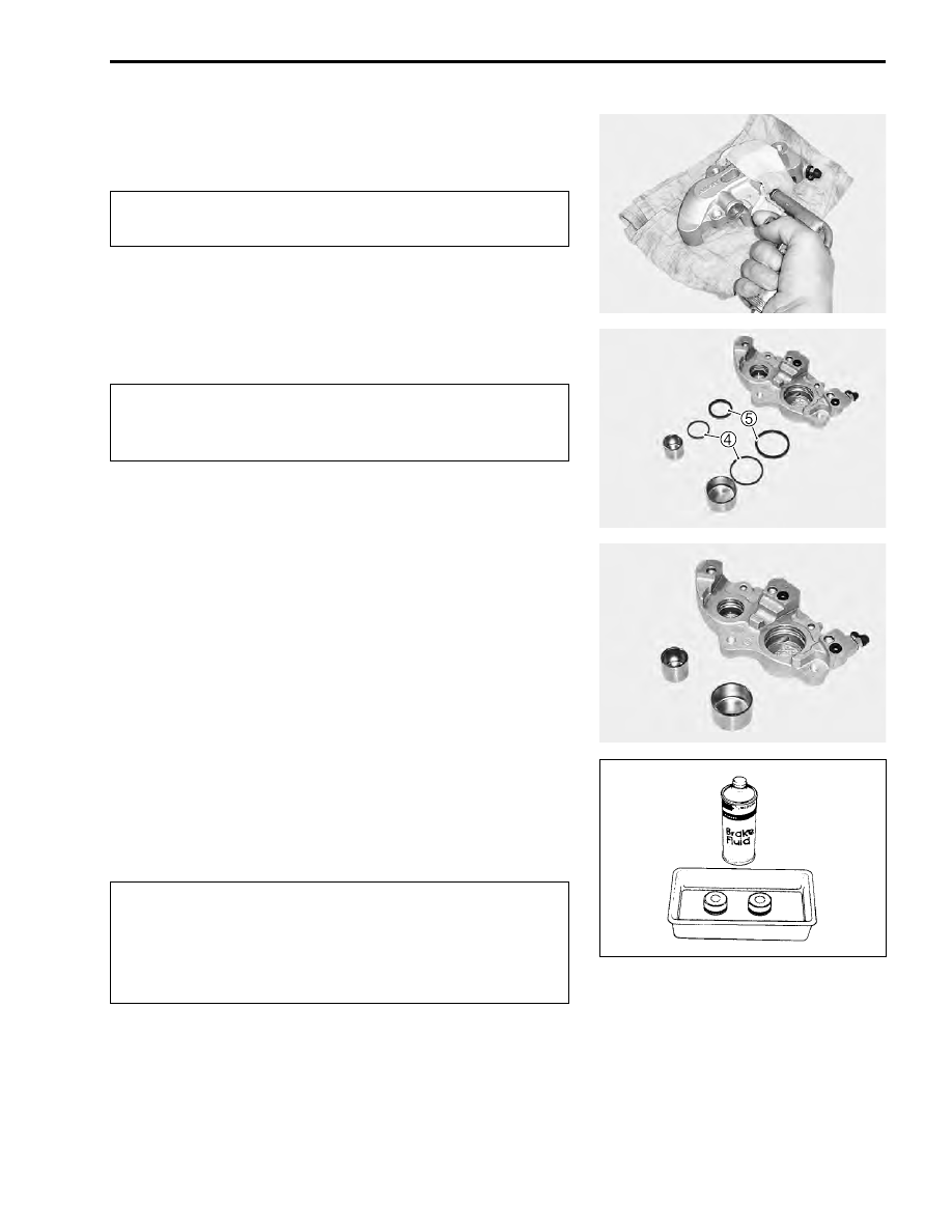
• Place a rag over the piston to prevent it from popping out and

then force out the piston using compressed air.

)

• Remove the dust seals 


4

 and piston seals 


5

.

$

CALIPER INSPECTION

• Inspect the caliper cylinder wall and piston surface for

scratch, corrosion or other damages.

• If any abnormal condition is noted, replace the caliper.

CALIPER REASSEMBLY AND REMOUNTING

• Reassemble and remount the caliper in the reverse order of

disassembly and removal.

• Pay attention to the following points:

$

*

Specification and classification: DOT 4

Do not use high pressure air to prevent piston dam-
age.

* Use care not to cause scratch on the cylinder bore.
* Do not reuse the piston seal and dust seal that have

been removed.

* Wash the caliper components with fresh brake fluid

before reassembly. Do not wipe off brake fluid after
washing the components.

* Replace the piston seal, dust seal and O-ring with

new ones with brake fluid applied.

7-28     CHASSIS

• Install the piston seal 


1

 and dust seal 


2

 as shown in the

illustration.

• Install the O-rings 


3

.

• Apply THREAD LOCK SUPER to the caliper housing bolts 


4

.

• Tighten the caliper housing bolts to the specified torque.

#

Caliper housing bolt: 23 N·m (2.3 kgf-m, 16.5 lb-ft)

(

99000-32130: THREAD LOCK SUPER “1360”

• Tighten the caliper mounting bolts 


5

 to the specified torque.

• With the hose ends contacted to the stoppers, tighten the

union bolts 


6

 to the specified torque.

#


5

 Caliper mounting bolt: 25 N·m (2.5 kgf-m, 18.0 lb-ft)


6

 Union bolt: 23 N·m (2.3 kgf-m, 16.5 lb-ft)

• For assembly procedure of brake hose. (

!

9-23)

• Fill the system with brake fluid and bleed air. (

!

2-19)

CHASSIS     7-29

• Perform the brake inspection after assembly has been com-

pleted. (

!

2-16)

BRAKE DISC INSPECTION

• Check the brake disc surface for scratch, crack or abnormal

wear.

• Measure the disc thickness at several positions using a

micrometer.

• If the measurement is less than the service limit or any abnor-

mal condition is noted, replace the disc with a new one. 
(

!

7-21)

&

Brake disc thickness: Service Limit: 4.0 mm (0.16 in)

%

09900-20205: Micrometer (0 – 25 mm)

• Measure the runout with a dial gauge.
• Replace the disc if the runout exceeds the service limit.

&

Brake disc runout: Service Limit: 0.30 mm (0.012 in)

%

09900-20607: Dial gauge (1/100 mm)
09900-20701: Magnetic stand

MASTER CYLINDER REMOVAL AND
DISASSEMBLY

• Remove the handle covers. (

!

7-11)

• Drain brake fluid from the front brake side reservoir.

(

!

2-17)

• Remove the rear view mirror 


1

.

• Disconnect the brake light switch lead wires 


2

.

• Remove the union bolt 


3

.

$

Place a rag under the union bolt so that brake fluid
may not contact the parts.

7-30     CHASSIS

• Remove the master cylinder 


4

.

• Remove the brake light switch 


5

 and brake lever 


6

.

• Remove the boot 


7

 and remove the snap ring 


8

.

• Remove the piston/cup set 


9

 and spring 


0

.

MASTER CYLINDER INSPECTION

• Inspect the cylinder wall, piston/cup set and spring for

scratch, corrosion or other damages.

• If any abnormal condition is noted, replace the inner parts or

master cylinder.


Content   ..  54  55  56  57   ..