Suzki Burgman AN400. Manual - part 54
CHASSIS 7-19
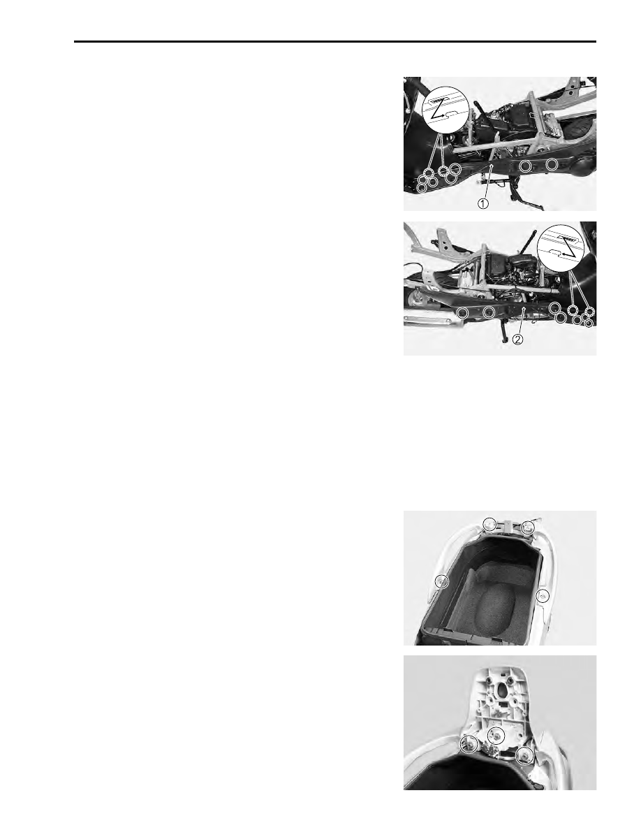
FOOT BOARD
• Remove the frame cover. (
!
7-18)
• Remove the bolts and screws.
• Remove the left foot board
1
.
• Remove the bolts and screws.
• Remove the right foot board
2
.
INSTALLATION
• Install the exterior parts in the revers order of removal.
• Pay attention to the following points:
PILLION RIDER HANDLE
• Apply THREAD LOCK to the pillion rider handle (left, right)
bolts.
"
99000-32050: THREAD LOCK “1342”
• Tighten the pillion rider handle bolts to the specified torque.
#
Pillion rider handle bolt: 23 N·m (2.3 kgf-m, 16.5 lb-ft)