Suzki Burgman AN400. Manual - part 48


  Index      Motorcycles     Suzki Burgman AN400 - service and repair manual 2002 year


Search            


Content   ..  46  47  48  49   ..


Suzki Burgman AN400. Manual - part 48


6-10     COOLING AND LUBRICATION SYSTEM
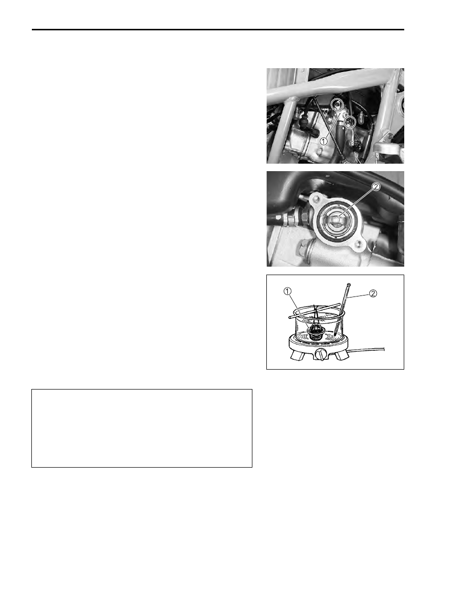
THERMOSTAT

REMOVAL

• Remove the frame cover. (

"

7-18)

• Remove the thermostat case 


1

.

• Remove the thermostat 


2

.

INSPECTION

• Check for crack or break on the thermostat.
• Immerse the thermostat in water contained in a pan as shown

and measure the valve start-to-open temperature when water
is heated gradually.

• If the thermostat valve opening temperature is not within the

specified range, replace the thermostat with a new one.

Thermostat valve start-to-open temperature: Approx.82 °C
(180 °F)

&

* Do not allow the thermostat 


1

 and thermometer 


2

to come in contact with the bottom of the pan.

* As the thermostat operating response to water tem-

perature change is gradual, do not raise water tem-
perature too quickly.

* The thermostat with its valve open even slightly

under normal temperature must be replaced.

COOLING AND LUBRICATION SYSTEM     6-11

• Continue to heat water until 95 °C (203 °F) is exceeded and

check for the thermostat valve lift when temperature is at 95
°C (203 °F).

• If the valve lift is out of specification or less then the specifica-

tion, replace the thermostat with a new one.

$

Thermostat valve lift: 3.0 mm (0.12 in)

INSTALLTATION

• Position the thermostat with the air bleeder hole 


A

 upside.

• Install the thermostat case 


1

.

%

Thermostat case bolt: 10 N·m (1.0 kgf-m 7.0 lb-ft)

NOTE:
Tighten the bolt together with the clamp 


2

 and secure the

high-tension cord with the clamp.

• After the thermostat has been installed, fill coolant and per-

form air bleeding. (

"

2-15)

Lift

6-12     COOLING AND LUBRICATION SYSTEM

WATER PUMP

REMOVAL AND DISASSEMBLY

• Drain engine coolant. (

"

6-3)

• Disconnect the water hose 


1

.

• Remove the water pump 


2

.

• Remove the water pump cover 


3

.

• Remove the E-ring 


4

.

• Remove the impeller together with the water pump shaft.

• Remove the mechanical seal 


5

 using the special tool.

#

09921-20240: Bearing remover set (

'

12)

COOLING AND LUBRICATION SYSTEM     6-13

• Remove the oil seal 


6

 using the special tool.

#

09913-50121: Oil seal remover

• Remove the bearing 


7

 using the special tool.

#

09921-20240: Bearing remover set (

'

10)

INSPECTION

• Visually check the mechanical seal surface for damage care-

fully.

• If any sign of leakage is noted, replace the mechanical seal

and as necessary together with the oil seal and bearing.

REASSEMBLY AND REMOUNTING

• Install the bearing 


1

.

#

09925-98221: Bearing installer

• Prior to installing the oil seal, apply SUZUKI SUPER GRE-

ASE to the lip.

NOTE:
Press-fit the oil seal 


2

 with the stamped mark side to face the

mechanical seal side.

(

99000-25010: SUZUKI SUPER GREASE “A” (Others)
99000-25030: SUZUKI SUPER GREASE “A” (USA)


Content   ..  46  47  48  49   ..