Suzki Burgman AN400. Manual - part 43


  Index      Motorcycles     Suzki Burgman AN400 - service and repair manual 2002 year


Search            


Content   ..  41  42  43  44   ..


Suzki Burgman AN400. Manual - part 43


5-10     FUEL SYSTEM AND THROTTLE BODY

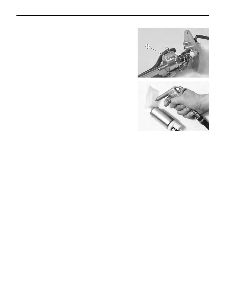
• Remove the fuel filter 


5

.

FUEL MESH FILTER INSPECTION AND 
CLEANING

• If the fuel mesh filter is clogged with sediment or rust, fuel will

not flow smoothly and loss in engine power may result.

• Blow the fuel mesh filter with compressed air.

NOTE:
If the fuel mesh filter is clogged with many sediment or rust,
replace the fuel filter cartridge with a new one.

FUEL SYSTEM AND THROTTLE BODY     5-11

FUEL LEVEL GAUGE INSPECTION

Measure resistance between the terminals when the float is at
the position instead below.

$

09900-25008: Multi-circuit tester set

• If the resistance measured is out of the specification, replace

the gauge with a new one.

• Fuel level meter inspection (

"

8-28)

Fuel float position

Resistance between terminals

F:98.4 mm (3.87 in) from 

tank mating face

Approx. 4 – 10 

1/2:176.1 mm (6.93 in) 

from tank mating face

Approx. 40 – 50 

E:244.7 mm (9.63 in) from 

tank mating face

Approx. 90 – 100 

F

98.4mm

(3.87in)

E

244.7mm

(9.63in)

176.1mm

(6.93in)

1

2

5-12     FUEL SYSTEM AND THROTTLE BODY

FUEL PUMP AND FUEL LEVEL GAUGE 
REASSEMBLY

• Reassemble the fuel pump and fuel level gauge reverse order

of disassembly.

• Pay attention to the following points:
• Apply thin coat of the engine oil to the O-ring.
• Install the fuel pressure regulator.

#

• Install the fuel filter 


1

.

#

• Apply thin coat of the engine oil to the O-ring.
• Install the O-ring 


2

 to the fuel tank.

#

• When installing the fuel pump assembly, first tighten all the

fuel pump assembly mounting bolts lightly in the ascending
order to numbers, and then tighten them to the specified
torque in the above tightening order.

%

Fuel tank bolt: 4.5 N·m (0.45 kgf-m, 3.3 lb-ft)

Use the new O-ring to prevent fuel leakage.

Install the fuel filter so that “OUT” mark 


A

 faces the

hose side.

Replace the O-ring with a new one.

FUEL SYSTEM AND THROTTLE BODY     5-13

THROTTLE BODY

ITEM

N·m

kgf-m

Ib-ft

A

3.5

0.35

2.5

1

Idle adjust screw

2

O-ring

3

Throttle body

4

O-ring

5

IAC valve

6

IAC valve cap

7

TP sensor

8

O-ring

9

O-ring

0

Insulator

A

O-ring

B

Intake pipe

C

O-ring

D

Fuel injector seal

E

Fuel injector

F

O-ring

G

Insulator

H

Throttle lever stopper screw

A

TP sensor mounting screw


Content   ..  41  42  43  44   ..