Suzki Burgman AN400. Manual - part 42


  Index      Motorcycles     Suzki Burgman AN400 - service and repair manual 2002 year


Search            


Content   ..  40  41  42  43   ..


Suzki Burgman AN400. Manual - part 42


5-6     FUEL SYSTEM AND THROTTLE BODY

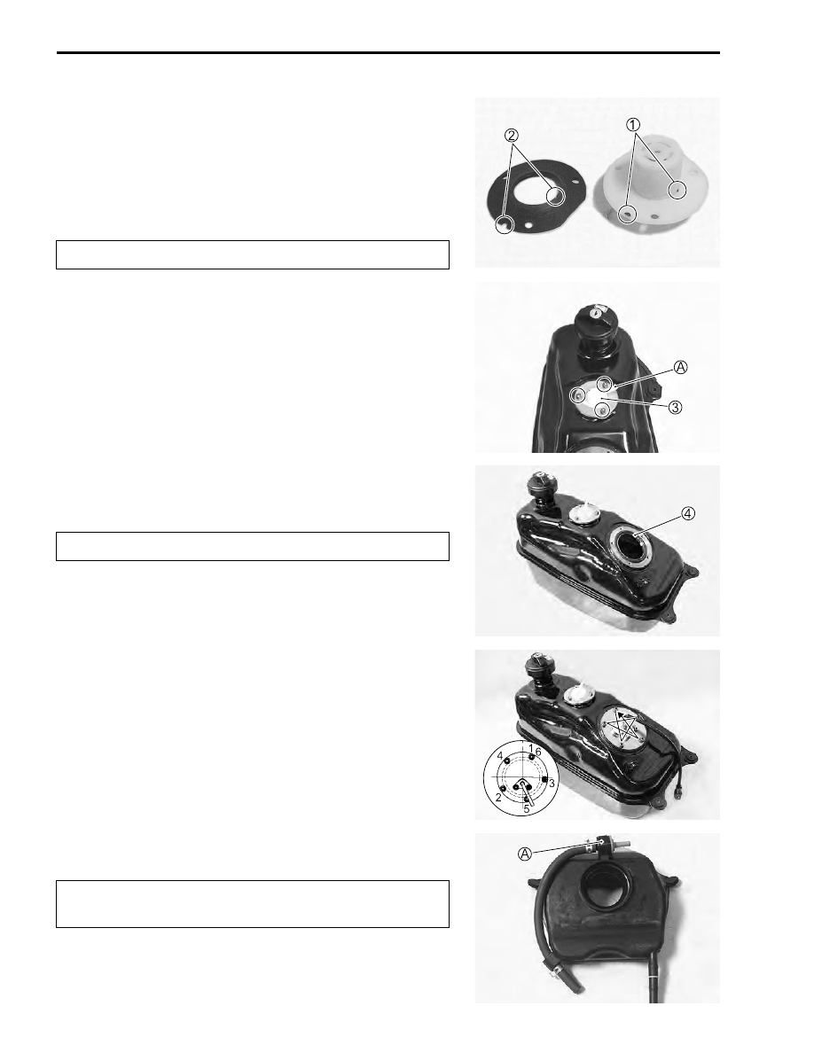
REASSEMBLY AND INSTALLATION

• Reassemble and installation the fuel tank in the reverse order

of removal and disassembly.

• Pay attention to the following points:
• Align the protrusion 


1

 of the fuel cut valve with the cutaway


2

 of the gasket.

#

• Install the fuel cut valve 


3

.

NOTE:
Install the fuel cut valve so that its hose fitting joint 


A

 faces the

right side of the vehicle.

• Tighten the fuel cut valve bolt to the specified torque.

%

Fuel cut valve bolt: 3.5 N·m (0.35 kgf-m, 2.5 lb-ft)

• Apply thin coat of the engine oil to the O-ring 


4

.

• Install the O-ring to the fuel tank.

#

• When installing the fuel pump assembly, first tighten all the

fuel pump assembly mounting bolts lightly in the ascending
order of numbers, and then tighten them to the specified
torque in the above tightening order.

%

Fuel pump mounting bolt: 4.5 N·m (0.45 kgf-m, 3.3 lb-ft)

• Install the FTPC valve.

#

Replace the gasket with a new one.

Replace the O-ring with a new one.

Connect the hose to the black part 


A

 of the FTPC

valve.

FUEL SYSTEM AND THROTTLE BODY     5-7

• Install the fuel hose.

#

• Tighten the fuel tank bolt to the specified torque.

%

Fuel tank bolt: 10 N·m (1.0 kgf-m, 7.0 lb-ft)

FUEL PRESSURE INSPECTION

• Remove the front frame cover. (

"

7-17)

• Place a rag under the fuel feed hose 


1

 and disconnect the

fuel feed hose 


1

 from the fuel tank.

• Install the special tools to the fuel tank.

$

09940-40211: Fuel pressure gauge adaptor
09940-40230: Fuel pressure gauge hose attachment
09915-77331: Oil pressure gauge
09915-74521: Oil pressure gauge hose

• Turn the ignition switch ON and check the fuel pressure.

&

Fuel pressure: Approx. 300 kPa (3.0 kgf/cm², 43 psi)

• If the fuel pressure is lower than the specification, inspect the

following items:

* Fuel hose leakage
* Clogged fuel filter
* Pressure regulator
* Fuel pump

Replace the O-ring 


4

 with a new one.

5-8     FUEL SYSTEM AND THROTTLE BODY

• If the fuel pressure is higher than the specification, inspect the

following items:

* Fuel pump check valve
* Pressure regulator

!

FUEL PUMP INSPECTION

• Turn the ignition switch ON and check that the fuel pump

operates for few seconds.

• If the fuel pumps motor does not make operating sound,

replace the fuel pump assembly or inspect the fuel pump relay
and tip over sensor.

FUEL DISCHARGE AMOUNT INSPECTION

!

• Remove the front box. (

"

7-14)

• Disconnect the fuel delivery pipe from the fuel injector.
• Place the measuring cylinder and insert the fuel delivery pipe

end into the measuring cylinder.

• Disconnect the ECM lead wire coupler.
• With the lead wire’s fastener 


A

 unlocked, pull out the power

source lead wire (Yellow with red tracer) 


1

.

• Apply 12 volts to the fuel pump for 10 seconds and measure

the amount of fuel discharged.

• If the pump does not discharge the amount specified, it

means that the fuel pump is defective or that the fuel filter is
clogged.

&

Fuel discharge amount:35 ml and more/10 sec.

(1.18/1.23 US/lmp oz)/10 sec.

NOTE:
The battery must be in fully charged condition.

* Before removing the special tools, turn the ignition

switch to OFF position and release the fuel pressure
slowly.

* Gasoline is highly flammable and explosive. Keep

heat, spark and flame away.

Gasoline is highly flammable and explosive. Keep
heat, spark and flame away.

Battery

FUEL SYSTEM AND THROTTLE BODY     5-9

FUEL PUMP RELAY INSPECTION

• Fuel pump relay is located behind the front panel.
• Remove the front leg shield.
• Remove the fuel pump relay.
• First, check the insulation between 


1

 and 


2

 terminals with

pocket tester. Then apply 12 volts to 


3

 and 


4

 terminals, 


+

 to


3

 and 


-

 to 


4

, and check the continuity between 


1

 and 


2

.

• If there is no continuity, replace it with a new one.

FUEL PUMP AND FUEL LEVEL GAUGE DIS-
ASSEMBLY

• Remove the fuel pump assembly. (

"

5-6)

• Remove the ground lead wire 


1

 and clamp 


2

.

• Remove the fuel pump 


3

.

• Remove the fuel pressure regulator 


4

.


Content   ..  40  41  42  43   ..