Suzki Burgman AN400. Manual - part 39
4-38 FI SYSTEM
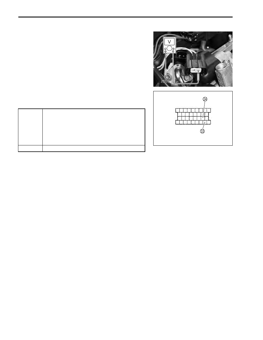
Step 2
1) Turn the ignition switch ON.
2) Measure the injector voltage between Y/R wire and ground.
$
Injector voltage: Battery voltage
(
+
Y/R –
-
Ground)
NOTE:
Injector voltage can be detected only 3 seconds after ignition
switch is turned ON.
!
09900-25008: Multi circuit tester set
&
Tester knob indication: Voltage (
'
)
Is the voltage OK?
YES
• Gr/W wire open or shorted to ground, or poor
N
or
W
connection.
• If wire and connection are OK, intermittent trou-
ble or faulty ECM.
• Recheck each terminal and wire harness for
open circuit and poor connection.
NO
Open circuit in the Y/R wire.
ECM Coupler