Suzki Burgman AN400. Manual - part 28


  Index      Motorcycles     Suzki Burgman AN400 - service and repair manual 2002 year


Search            


Content   ..  26  27  28  29   ..


Suzki Burgman AN400. Manual - part 28


ENGINE     3-75

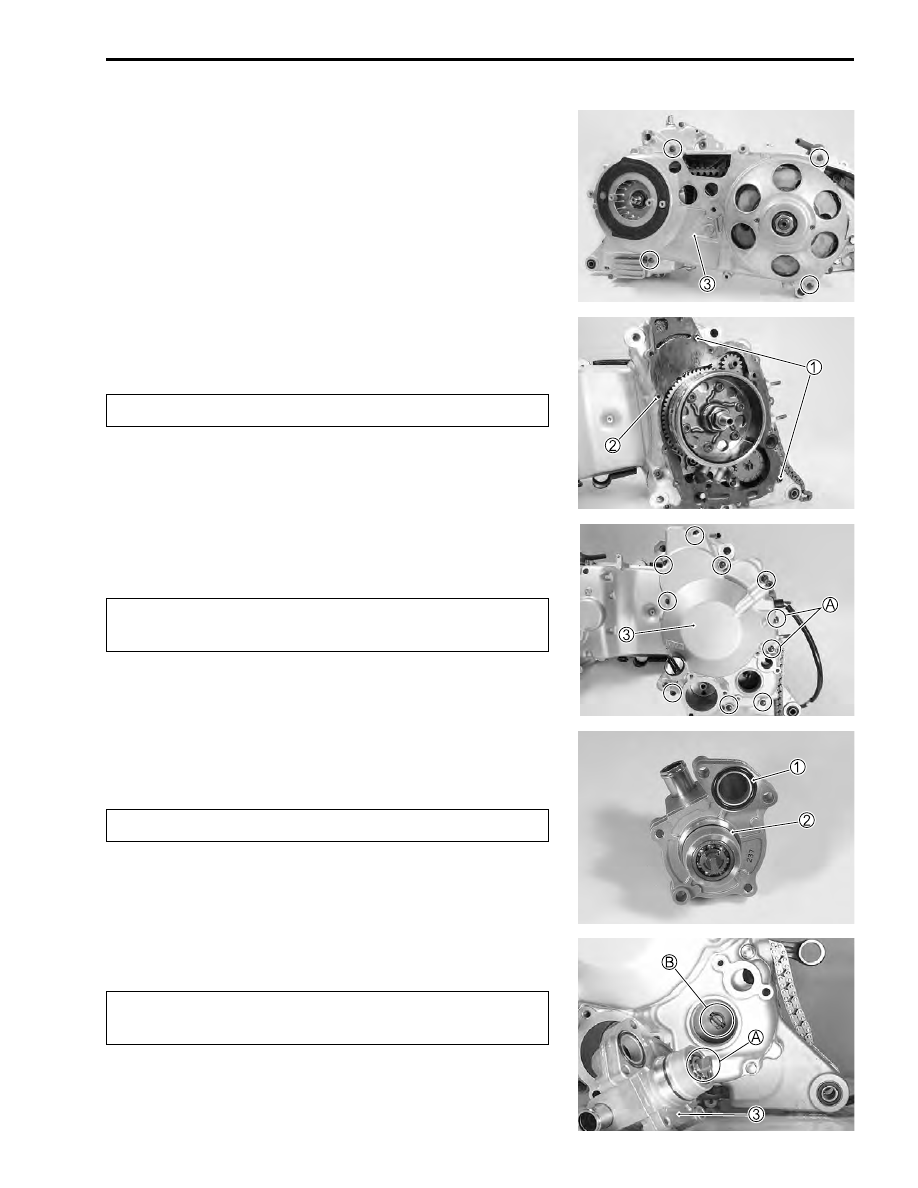
• Install the clutch inner cover 


3

.

• Tighten the clutch inner cover bolts to the specified torque.

#

Clutch inner cover bolt: 11 N·m (1.1 kgf-m, 8.0 lb-ft)

GENERATOR COVER

• Install the dowel pins 


1

 and gasket 


2

.

$

• Install the generator cover 


3

.

• Tighten the generator cover bolts to the specified torque.

$

#

Generator cover bolt: 11 N·m (1.1 kgf-m, 8.0 lb-ft)

WATER PUMP

• Install the O-rings 


1


2

 to the water pump.

$

• Apply a small amount of engine oil to the O-rings.

• Install the water pump 


3

.

$

Replace the gasket with a new one.

* Fit the gasket washer to the bolts 


A

.

* Replace the gaskets with new ones.

Replace the O-rings with new ones.

Align the flats 


A

 of the water pump shaft end with the

slot 


B

 of the oil pump shaft.

3-76     ENGINE

• Tighten the water pump bolts to the specified torque.

#

Water pump bolt: 10 N·m (1.0 kgf-m, 7.0 lb-ft)

OIL FILTER

• Install the O-ring 


1

.

$

• Install the oil filter 


2

.

$

• Install the O-ring 


3

.

• Install the oil filter cap 


4

.

• Tighten the oil filter cap bolts to the specified torque.

$

#

Oil filter cap bolt: 10 N·m (1.0 kgf-m, 7.0 lb-ft)

PISTON RING

• Install the piston rings in the order of oil ring, 2nd ring and top

ring.

• To install the oil ring, fit the spacer 


1

 first and then the side

rails 


2

.

Replace the O-ring with a new one.

Position the oil filter so that the valve 


A

 comes out-

side.

Position the triangle mark 


B

 of oil filter cap comes up

side.

ENGINE     3-77

$

• Be careful not to mistake the top ring 


3

 and the second ring


4

, the sectional form is different.

• Face the side with the stamped mark 


A

 upward when assem-

bling.

• After installing all the piston rings, check that each ring rotates

smoothly.

• To prevent poor compression or oil leaking up to the cylinder

inside, position each ring end gap as shown in the right figure.


A

 Second ring/side rail (lower side)


B

 Side rail (upper side)


C

 Top ring/spacer

PISTON

• Lightly coat the piston pin with SUZUKI MOLY PASTE when

inserting.

.

99000-25140: SUZUKI MOLY PASTE

• When installing the piston, turn the concaved part 


A

 on the

piston head to exhaust side.

* When installing the spacer, be careful so that the

both edges are not overlapped.

* When installing the piston ring, be careful not to

damage the piston.

* Do not expand the piston ring excessively since it is

apt to be broken down.

INCORRECT

CORRECT

Top ring

2nd ring

EX

IN

120˚

120˚

120˚

3-78     ENGINE

• Install the circlip 


1

.

$

CYLINDER

• Install the dowel pins 


1

 and a new gasket 


2

 to the crank-

case.

$

• Coat the cylinder wall and piston surface with oil.
• Install the cylinder 


3

.

$

• Temporary tighten the cylinder nuts 


4

.

CAM CHAIN GUIDE

• Install the cam chain guide 


1

.

$

CYLINDER HEAD

• Place the dowel pins 


1

 and cylinder gasket 


2

 on the crank-

case.

$

* Replace the circlip with a new one.
* Place a piece of rag under the piston when installing

the circlip to prevent it from falling into the crank-
case.

* The circlip end gap must be positioned so as not to

coincide with the piston pin bore cutaway.

Replace the gasket with a new one.

When inserting the piston into the cylinder, use care
not to break the piston ring.

When installing the cam chain guide, check that the
chain is properly engaged with the crankshaft
sprocket.

Replace the gasket with a new one.


Content   ..  26  27  28  29   ..