Suzki Burgman AN400. Manual - part 26
ENGINE 3-67
• Tighten the crankcase bolts(8mm)diagonally and evenly in
two stages; initial tightening and final tightening.
Crankcase bolt
#
Initial tightening:8 mm 13 N·m (1.3 kgf-m, 9.5 lb-ft)
Final tightening: 8 mm 22 N·m (2.2 kgf-m, 16.0 lb-ft)
6 mm 11 N·m (1.1 kgf-m, 8.0 lb-ft)
NOTE:
After crankcase bolts have been tightened, check it crankshaft
rotate smoothly
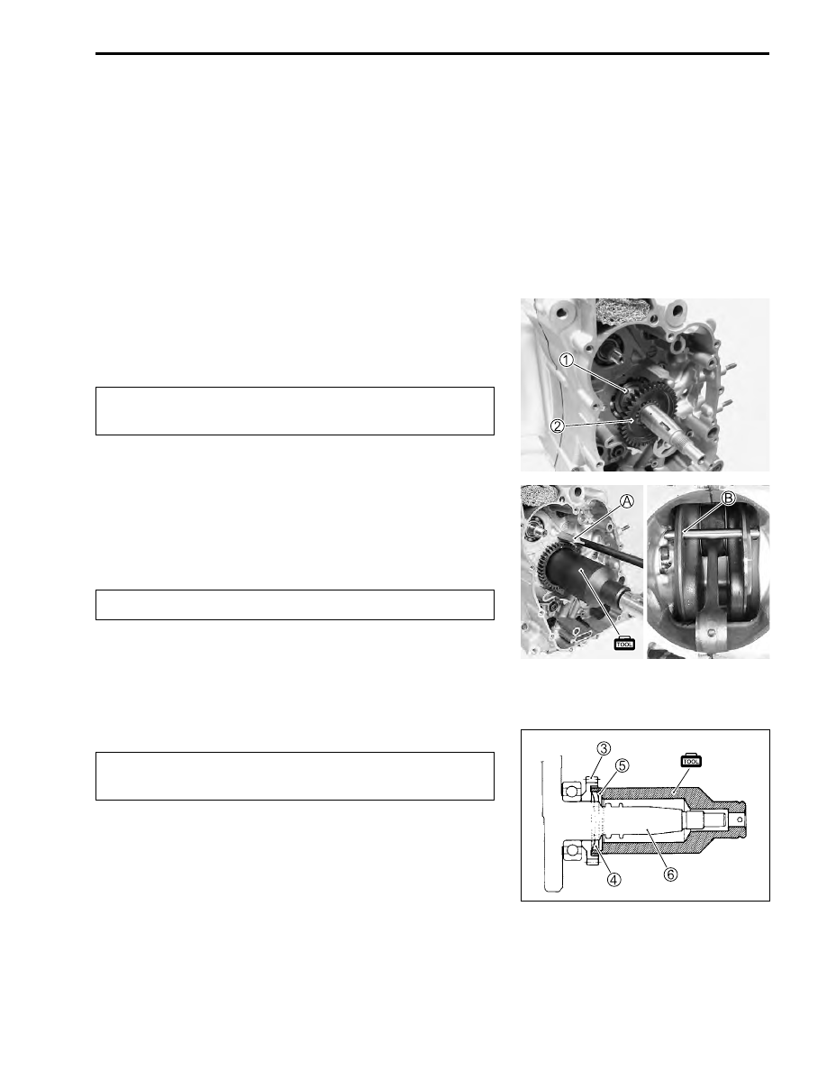
BALANCER GEAR
• Insert the pin
1
.
• Install the balancer drive gear
2
.
$
• Insert a proper steel rod into the crankcase hole
A
and pass
through the crankshaft wed holes
B
in order to prevent the
crankshaft from turning.
• Install the wave washer.
$
• Using the special tool, tighten the balancer drive gear nut to
the specified torque.
%
09922-21410: Long socket (46 mm)
#
Balancer drive gear nut: 150 N·m (15 kgf-m, 11 lb-ft)
$
3
Balancer drive gear
4
Wave washer
5
Balancer drive gear unt
6
Crankshaft
Make sure to align the slot of the balancer drive gear
with the pin.
Pay attention to the direction of the wave washer.
Pay attention to the direction of balancer drive gear
nut.