Volkswagen Golf / Golf GTI / Golf Variant. Service manual - part 988
5.2.2
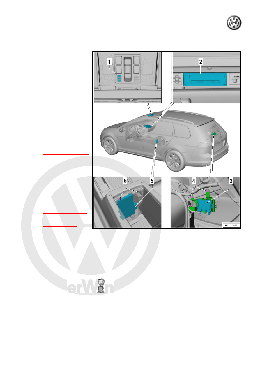
Component Location Overview - Telephone System, Wagon
1 - Telephone Microphone -
R38-
❑ In the Front Interior
Lamp - W1-
❑ Removing and instal‐
ling. Refer to
2 - Information Electronics
Control Module 1 - J794-
❑ In the glove compart‐
ment
❑ Connector assignment.
Refer to ⇒ Wiring dia‐
grams, Troubleshooting
& Component locations.
❑ Removing and instal‐
ling. Refer to
.
3 - Mobile Communication 2-
Way Signal Amplifier - J984-
❑ Behind the luggage
compartment trim panel
on the right side
❑ Removing and instal‐
ling. Refer to
4 - Bolt
❑ 2 Nm
❑ Quantity: 2
5 - Storage Compartment with Cell Phone Interface - R265-
❑ Removing and installing. Refer to
⇒ “5.5 Storage Compartment with Cell Phone Interface R265 , Removing and Installing”, page 44
6 - Bolt
❑ 2 Nm
❑ Quantity: 2