Volkswagen Golf / Golf GTI / Golf Variant. Service manual - part 943
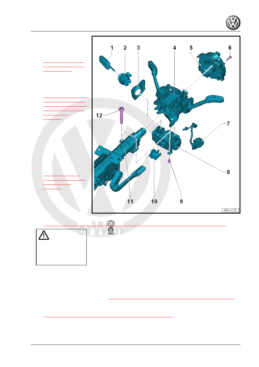
1 - Ignition Key
2 - Lock Cylinder
❑ Removing and instal‐
ling. Refer to
.
3 - Anti-Theft Immobilizer
Reader Coil - D2-
❑ Removing and instal‐
ling. Refer to
.
4 - Mount
❑ With Turn Signal Switch
- E2- / Windshield Wiper
Intermittent Mode
Switch - E22-
❑ With cruise control: with
Cruise Control Switch -
E45-
❑ Removing and instal‐
ling. Refer to
.
5 - Steering Column Electron‐
ics Control Module - J527-
❑ With Airbag Spiral
Spring/Return Spring
with Slip Ring - F138-
❑ Removing and installing. Refer to
⇒ “8.6 Steering Column Electronics Control Module J527 , Removing and Installing”, page 187
.
Caution
Risk of damaging the re‐
turn ring.
♦
The return spring with
slip ring must not be
turned after removing.
6 - Screw
❑ 1 Nm
❑ Quantity: 3
7 - Ignition/Starter Switch - D-
❑ Removing and installing. Refer to
⇒ “8.4 Ignition/Starter Switch, Removing and Installing”, page 181
.
8 - Steering Lock Housing
❑ Removing and installing. Refer to
⇒ “8.11 Steering Lock Housing, Removing and Installing”, page 195
.
9 - Screw
❑ 1 Nm