Volkswagen Golf / Golf GTI / Golf Variant. Service manual - part 861


  Index      Volkswagen     Volkswagen Golf / Golf GTI / Golf Variant - service and repair manual 2013 year


Search            copyright infringement  


Content   ..  859  860  861  862   ..


Volkswagen Golf / Golf GTI / Golf Variant. Service manual - part 861


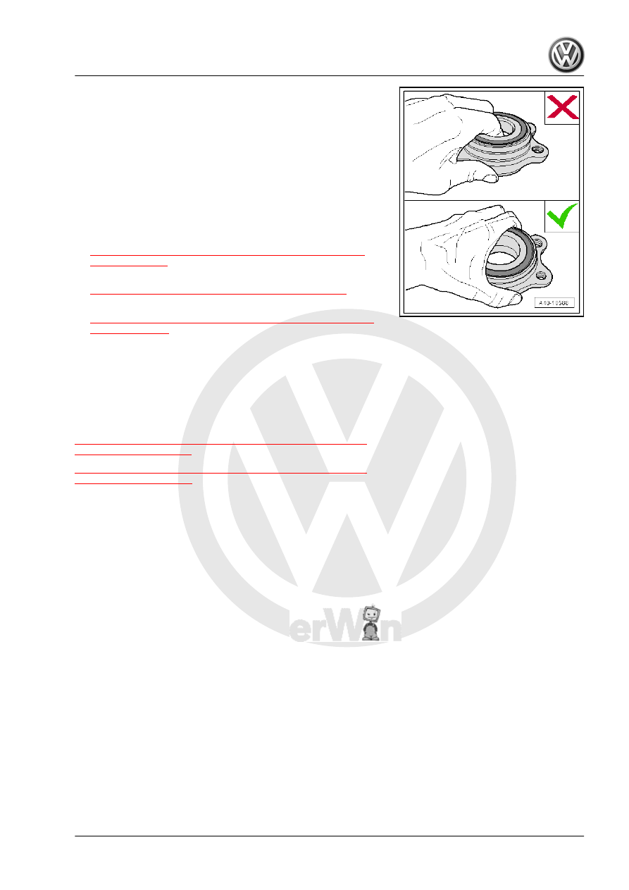
• Never reach into the inside when lifting the wheel bearing.
• Hold the wheel bearing only on the outside.
The same procedure also applies to the wheel bearing without a

wheel hub.
Installing
Install in reverse order of removal. Note the following:
• Only fasten the bolted connections on the wheel bearing hous‐

ing in the curb weight position.

Tightening Specifications
♦ Refer to

⇒ “7.1.3 Overview - Wheel Bearing, Multi-Link Suspension,

AWD”, page 212

♦ Refer to

⇒ “1.1 Wheel Bolt Tightening Specifications”, page 286

♦ Refer to

⇒ “8.2 Drive Axle Threaded Connection, Loosening and Tight‐

ening”, page 241

♦ Refer to ⇒  Brake System; Rep. Gr.  46 ; Rear Brakes; Over‐

view - Rear Brakes .

– Evaluating Need for Axle Alignment. Refer to the table.

7.5

Wheel Bearing Housing Bonded Rubber

Bushing, Replacing

⇒ “7.5.1 Wheel Bearing Housing Bonded Rubber Bushing, Re‐

placing, FWD”, page 229
⇒ “7.5.2 Wheel Bearing Housing Bonded Rubber Bushing, Re‐

placing, AWD”, page 231

7.5.1

Wheel Bearing Housing Bonded Rubber

Bushing, Replacing, FWD

Special tools and workshop equipment required
♦ Subframe Bushing Tool Kit - 3301-
♦ Bearing Installer - Control Arm - 3346-
♦ Bearing Installer - Carrier Bearing - 3350-
♦ Vibration Damper Assembly Tool - T10356-
♦ Torque Adapter - 3390-
♦ Torque Wrench 1332 40-200Nm - VAG1332-
Removing
– Loosen the wheel bolts.
– Raise the vehicle.
– Remove the wheel.

Vehicles with Level Control System Sensor
– Remove the bolts -1-.
– Remove the Left Rear Level Control System Sensor -2- brack‐

et.

Vehicles with Stone Chip Protection
– Remove the expanding rivets -1-.
– Remove the bolts -2- for the stone chip protection -3-.
Continuation for All Vehicles.
– Remove the spring. Refer to

⇒ “6.4 Spring, Removing and Installing”, page 202

 .

Pressing Out Bonded Rubber Bushing
1 - -3346/3-
2 - Thrust piece from the -3301-
3 - -3390-
4 - Sleeve from -3350-
5 - Nut
6 - -3346/2-
– Remove the bonded rubber bushing by turning the -3346/3-

-1-. While doing so counterhold on the -3346/2- -6-.

Bonded Rubber Bushing, Installing
1 - -3346/3-
2 - Thrust piece from the -3301-
3 - -T10356/5-
4 - Bonded Rubber Bushing
5 - Wheel Bearing Housing
6 - Sleeve from -3350-
7 - Nut
8 - -3346/2-
– Install the bonded rubber bushing until it stops by turning the

-3346/3- -1-. While doing so counterhold on the -3346/2- -8-.

Note

Do not use lubricant!

Insert the bearing carefully so that it is not tilted.

Installing
Install in reverse order of removal while noting the following:
Tightening Specifications
♦ Refer to 

⇒ “7.1 Overview - Wheel Bearing”, page 209

♦ Refer to

⇒ “6.1.2 Overview - Suspension Strut, Shock Absorber and

Spring, Multi-Link Suspension”, page 192

♦ Refer to

⇒ “4.1.1 Overview - Stabilizer Bar, Multi-Link Suspension,

FWD”, page 177

• Only fasten the threaded connections to the lower transverse

link in the curb weight position.

• For vehicles with a level control system sensor, perform the

basic setting for the wheel damping electronics using the Ve‐

hicle Diagnostic Tester.

• For vehicles with a level control system sensor, perform a

headlamp basic setting. Refer to ⇒  Electrical Equipment; Rep.

Gr.  94 ; Headlamp; Headlamp, Adjusting .

7.5.2

Wheel Bearing Housing Bonded Rubber

Bushing, Replacing, AWD

Special tools and workshop equipment required
♦ Subframe Bushing Tool Kit - 3301-
♦ Bearing Installer - Carrier Bearing - 3350-
♦ Torque Wrench 1332 40-200Nm - VAG1332-
♦ Press Tool For Viscous Fan - 3367-
♦ Torque Adapter - 3390-
♦ Bearing Installer - Control Arm - 3346-
Removing
– Loosen the wheel bolts.

– Raise the vehicle.
– Remove the wheel.
Vehicles with Level Control System Sensor
– Remove the bolts -1-.
– Remove the Left Rear Level Control System Sensor -2- brack‐

et.

Vehicles with Stone Chip Protection
– Remove the expanding rivets -1-.
– Remove the bolts -2- for the stone chip protection -3-.
Continuation for All Vehicles.
– Remove the spring. Refer to

⇒ “6.4 Spring, Removing and Installing”, page 202

 .

Pressing out Bonded Rubber Bushing
1 - Bearing Installer - Control Arm - Nut - 3346/3-
2 - Thrust piece from the Subframe Bushing Tool Kit - 3301-
3 - Torque Adapter - 3390-
4 - Sleeve from Bearing Installer - Carrier Bearing - 3350-
5 - Nut
6 - Bearing Installer - Control Arm - Spindle - 3346/2-
– Remove the bonded rubber bushing by turning the Bearing

Installer - Control Arm - Nut - 3346/3- -1-. While doing so

counterhold on the Bearing Installer - Control Arm - Spindle -

3346/2- -6-.

Bonded Rubber Bushing, Installing


Content   ..  859  860  861  862   ..