Volkswagen Golf / Golf GTI / Golf Variant. Service manual - part 857


  Index      Volkswagen     Volkswagen Golf / Golf GTI / Golf Variant - service and repair manual 2013 year


Search            copyright infringement  


Content   ..  855  856  857  858   ..


Volkswagen Golf / Golf GTI / Golf Variant. Service manual - part 857


7.2

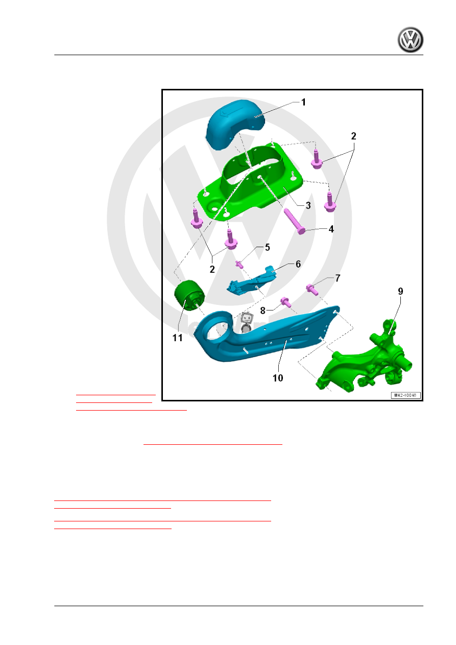
Overview - Trailing Arm

1 - Cover
2 - Bolt

❑ 50 Nm + 45°
❑ Replace after removal

3 - Mounting Bracket
4 - Bolt

❑ 90 Nm + 90°
❑ Replace after removal

5 - Rivet

❑ Replace after removal

6 - Bracket

❑ For the rear brake cable

7 - Bolt

❑ 70 Nm +90°
❑ Replace after removal
❑ M14 x 1.5

8 - Bolt

❑ 70 Nm + 90°
❑ Replace after removal
❑ M12 x 1.5

9 - Wheel Bearing Housing

❑ There are different ver‐

sions. Refer to the Parts

Catalog.

10 - Trailing Arm

❑ Removing and instal‐

ling. Refer to

⇒ “7.6 Trailing Arm with

Mounting Bracket, Re‐

moving and Installing”, page 234

11 - Bonded Rubber Bushing

❑ Note the installation position
❑ Replacing. Refer to 

⇒ “7.7 Trailing Arm, Servicing”, page 237

7.3

Wheel Bearing Housing, Removing and

Installing

⇒ “7.3.1 Wheel Bearing Housing, Removing and Installing, Multi-

Link Suspension, FWD”, page 213
⇒ “7.3.2 Wheel Bearing Housing, Removing and Installing, Multi-

Link Suspension, AWD”, page 217

7.3.1

Wheel Bearing Housing, Removing and

Installing, Multi-Link Suspension, FWD

Special tools and workshop equipment required
♦ Torque Wrench 1332 40-200Nm - VAG1332-
♦ Engine and Gearbox Jack - VAS6931-

Removing
– Loosen the wheel bolts.
– Raise the vehicle.
– Remove the wheel.
– Remove the wheel bearing unit. Refer to

⇒ “7.4 Wheel Bearing Unit, Removing and Installing”,

page 222

 .

– Remove the heat shield. Refer to ⇒  Brake System; Rep. Gr. 

46 ; Overview - Rear Brakes .

Vehicles with Level Control System Sensor
– Remove the spring. Refer to

⇒ “6.4 Spring, Removing and Installing”, page 202

 .

– Remove the bolts -1-.
– Remove the Left Rear Level Control System Sensor -2- brack‐

et.

Vehicles with Stone Chip Protection
– Remove the expanding rivets -1-.
– Remove the bolts -2- for the stone chip protection -3-.
Continuation for all Vehicles
– Disconnect the connector from the ABS speed sensor.

– Secure both sides of the vehicle on the hoist arms using -

T10038- .

1 - -T10038-

WARNING

The vehicle could slide off the hoist if it is not secured.

– Place the -VAS6931- -1- under the tie rod and push lightly up‐

ward.

– Remove the bolts -2 and 3- one after the other.
– Remove the -VAS6931- -1- from under the tie rod.

– Unscrew the nut -1- and remove the washer -2-.
– Remove the bolt -3-.

– Remove the bolt -1-.
– Remove the wheel bearing housing -2-.
Installing
Install in reverse order of removal while noting the following:
Complete the following steps in the exact order specified.

– Insert the wheel bearing housing -2-.
– Insert the bolt -1- and tighten hand-tight.

– Insert the bolt -3-.
– Slide on the washer -2-.
– Tighten the nut -1- hand-tight.

– Place the -VAS6931- -1- under the tie rod and push lightly up‐

ward.

– Install the bolts -2- and -3- by hand.
– Remove the -VAS6931- -1- from under the tie rod.
– Install the heat shield. Refer to ⇒  Brake System; Rep. Gr.  46 ;

Overview - Rear Brakes .

– Install the wheel bearing unit. Refer to

⇒ “7.4 Wheel Bearing Unit, Removing and Installing”,

page 222

 .

Only fasten the threaded connections on the wheel bearing hous‐

ing in the curb weight position.

– Tighten the bolt -1-.

– Tighten the nut -1-.
– Remove the -VAS6931- with the -T10149- from the wheel hub.


Content   ..  855  856  857  858   ..