Volkswagen Golf / Golf GTI / Golf Variant. Service manual - part 854
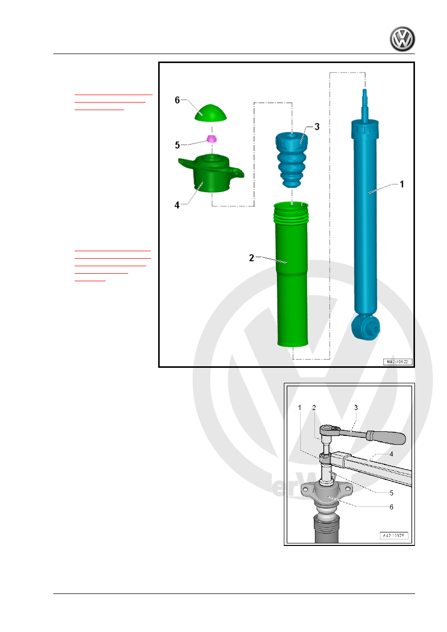
1 - Shock Absorber
❑ Removing and instal‐
ling. Refer to
.
❑ Always vent and drain
faulty shock absorbers
before disposal.
❑ Removed shock ab‐
sorber, checking
2 - Protective Tube
3 - Stop Buffer
4 - Shock Absorber Mount
5 - Nut
❑ 25 Nm
❑ Replace after removal
❑ Loosening and tighten‐
ing. Refer to
6 - Cover
Loosening and Tightening Bolted Connection for Shock Absorber
Mount
1 - Commercially available ring spanner insert, such as “Hazet
6630c-21”
2 - Shock Absorber Set - Extension with Counter Holder 1 -
T10001/9-
3 - Ratchet (commercially available)
4 - Torque Wrench 1331 5-50Nm - VAG1331-
5 - Shock Absorber Set - Socket - T10001/1-
6 - Shock absorber mount
Installation is the reverse of removal, with special attention to the
following: