Volkswagen Golf / Golf GTI / Golf Variant. Service manual - part 851


  Index      Volkswagen     Volkswagen Golf / Golf GTI / Golf Variant - service and repair manual 2013 year


Search            copyright infringement  


Content   ..  849  850  851  852   ..


Volkswagen Golf / Golf GTI / Golf Variant. Service manual - part 851


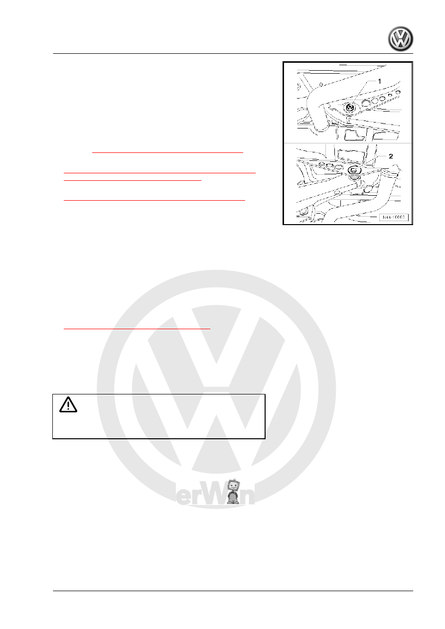
– Mark the position of the eccentric screw -2- in relation to the

subframe, for example using a felt-tip pen.

– Unscrew the nut -1- and remove the bolt -2-.
– Remove lower transverse link.
Installing
Install in reverse order of removal while noting the following:
Tightening Specifications
♦ Refer to 

⇒ “5.1 Overview - Transverse Link”, page 181

♦ Refer to

⇒ “2.4 Left/Right Rear Level Control System Sensor G76 /

G77 , Removing and Installing”, page 282

♦ Refer to

⇒ “1.1 Wheel Bolt Tightening Specifications”, page 286

♦ Rear exhaust system. Refer to ⇒  Rep. Gr.  26 ; Exhaust Pipes/

Mufflers; Overview - Muffler .

• Observe the mark made for the eccentric screw -2- in relation

to the subframe.

• Only fasten the transverse link in the curb weight position.
• For vehicles with a level control system sensor, perform the

basic setting for the wheel damping electronics using the Ve‐

hicle Diagnostic Tester.

• For vehicles with a level control system sensor, perform a

headlamp basic setting. Refer to ⇒  Electrical Equipment; Rep.

Gr.  94 ; Headlamp; Headlamp, Adjusting .

– Perform an axle alignment. Refer to

⇒ “3.5 Axle Alignment Procedure”, page 302

 .

5.5

Tie Rod, Removing and Installing

Special tools and workshop equipment required
♦ Torque Wrench 1331 5-50Nm - VAG1331-
♦ Torque Wrench 1332 40-200Nm - VAG1332-

Caution

This procedure contains mandatory replaceable parts. Refer

to component overview prior to starting procedure.

Mandatory Replacement Parts
♦ Bolt - Stabilizer Bar to Subframe
♦ Bolt- Tie Rod to Wheel Bearing Housing
♦ Bolt - Tie Rod to Subframe
♦ Nut - Tie Rod to Subframe
Removing
– Loosen the wheel bolts.
– Raise the vehicle.
– Remove the wheel.

– Remove the bolts -arrows- for the stabilizer bar -1-

– Loosen the nut -1- and the bolt -3- several turns.
– Remove the bolt -3-.
– Remove the nut -1- and then remove the bolt -4- to the rear.
– Remove the tie rod -2-.
Installing
Install in reverse order of removal. Note the following:
Tightening Specifications
♦ Refer to 

⇒ “5.2 Overview - Tie Rod”, page 184

♦ Refer to 

⇒ “4.1 Overview - Stabilizer Bar”, page 177

♦ Refer to

⇒ “1.1 Wheel Bolt Tightening Specifications”, page 286

• The tie rods may only be fastened when the dimension be‐

tween wheel hub center and lower edge of wheel housing,

measured before assembly, is achieved.

– Perform an axle alignment.

6

Suspension Strut/Shock Absorber,

Spring

⇒ “6.1 Overview - Suspension Strut, Shock Absorber and Spring”,

page 191
⇒ “6.2 Shock Absorber, Removing and Installing”, page 193
⇒ “6.3 Shock Absorber, Servicing”, page 200
⇒ “6.4 Spring, Removing and Installing”, page 202

6.1

Overview - Suspension Strut, Shock Ab‐

sorber and Spring

⇒ “6.1.1 Overview - Suspension Strut, Shock Absorber and

Spring, Torsion Beam Axle”, page 191
⇒ “6.1.2 Overview - Suspension Strut, Shock Absorber and

Spring, Multi-Link Suspension”, page 192

6.1.1

Overview - Suspension Strut, Shock Absorber and Spring, Torsion Beam

Axle

1 - Bolt

❑ 50 Nm + 45°
❑ Replace after removal

2 - Shock Absorber

❑ Removing and instal‐

ling. Refer to

⇒ “6.2 Shock Absorber,

Removing and Instal‐

ling”, page 193

❑ Always vent and drain

faulty shock absorbers

before disposal.

3 - Upper Spring Support

❑ Place on body “tab”.

4 - Spring

❑ Removing and instal‐

ling. Refer to

⇒ “6.4.1 Spring, Remov‐

ing and Installing, Tor‐

sion Beam Axle”,

page 202

5 - Clamping Ring

❑ Press in the clamping

ring until flush after in‐

stalling the stone chip

protection.

6 - Low Spring Support

❑ Spring end rotated up to

stop

❑ Insert the pin into the

hole in the spring mount

on the axle beam when

installing.

7 - Axle Beam
8 - Stone Chip Protection
9 - Expanding Rivet
10 - Bolt

❑ 70 Nm + 180°
❑ Replace after removal
❑ Always tighten threaded connection in curb weight position

6.1.2

Overview - Suspension Strut, Shock Absorber and Spring, Multi-Link Sus‐

pension

1 - Bolt

❑ 50 Nm + 45°
❑ Replace after removal

2 - Shock Absorber

❑ Removing and instal‐

ling. Refer to

⇒ “6.2 Shock Absorber,

Removing and Instal‐

ling”, page 193

❑ Observe the installation

position of the cable tie

closure

❑ Always vent and drain

faulty shock absorbers

before disposal.

3 - Upper Spring Support

❑ Place on body “tab”.

4 - Spring

❑ Removing and instal‐

ling. Refer to

⇒ “6.4 Spring, Remov‐

ing and Installing”, page

202

5 - Clip

❑ Serves as an assembly

aid

6 - Low Spring Support

❑ Spring end rotated up to

stop

❑ When assembling, in‐

sert the pin into the

spring mount opening

on the lower transverse

link -arrow-.

7 - Lower Transverse Link
8 - Nut

❑ 70 Nm + 180°
❑ Replace after removal
❑ Always tighten threaded connection in curb weight position


Content   ..  849  850  851  852   ..