Volkswagen Golf / Golf GTI / Golf Variant. Service manual - part 848
4
Stabilizer Bar
⇒ “4.1 Overview - Stabilizer Bar”, page 177
⇒ “4.2 Stabilizer Bar, Removing and Installing”, page 178
⇒ “4.3 Coupling Rod, Removing and Installing”, page 179
4.1
Overview - Stabilizer Bar
⇒ “4.1.1 Overview - Stabilizer Bar, Multi-Link Suspension, FWD”,
page 177
⇒ “4.1.2 Overview - Stabilizer Bar, Multi-Link Suspension, AWD”,
4.1.1
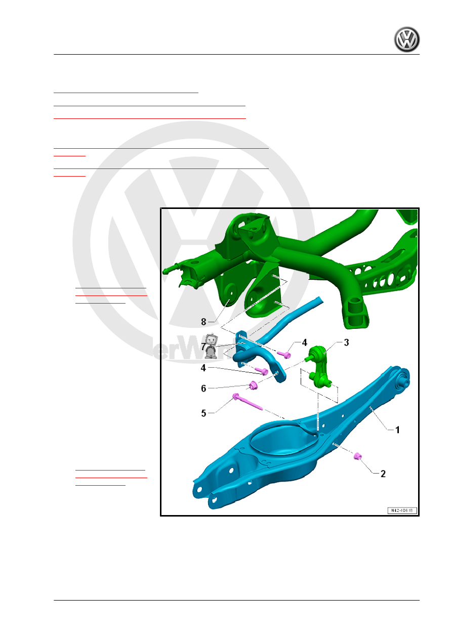
Overview - Stabilizer Bar, Multi-Link Suspension, FWD
1 - Lower Transverse Link
2 - Nut
❑ 20 Nm + 180°
❑ Replace after removal
3 - Coupling Rod
❑ Removing and instal‐
ling. Refer to
.
4 - Bolt
❑ 20 Nm + 90°
❑ Replace after removal
❑ Install evenly
5 - Bolt
❑ Replace after removal
6 - Nut
❑ 55 Nm
❑ Counterhold at connect‐
ing link socket head
when tightening
7 - Stabilizer Bar
❑ With rubber bushings
❑ Removing and instal‐
ling. Refer to
.
8 - Subframe