Volkswagen Golf / Golf GTI / Golf Variant. Service manual - part 817


  Index      Volkswagen     Volkswagen Golf / Golf GTI / Golf Variant - service and repair manual 2013 year


Search            copyright infringement  


Content   ..  815  816  817  818   ..


Volkswagen Golf / Golf GTI / Golf Variant. Service manual - part 817


Installing Spring
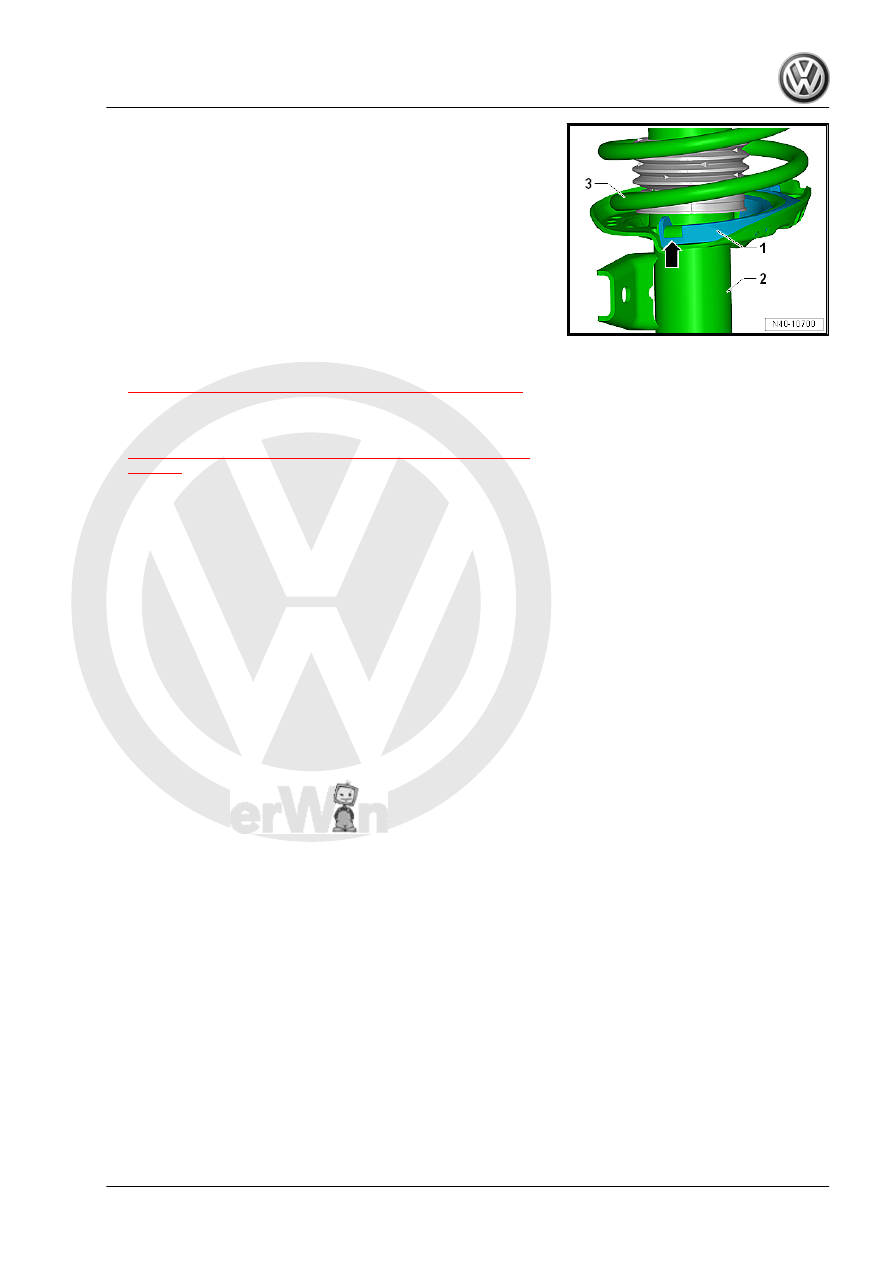
– Place the spring support -1- in the shock absorber -2-.
– Place the coil spring -3- with the Spring Compressor Kit -

Spring Tensioner - VAG1752/1- on the lower spring support.

End of spring coil must rest against stop -arrow-.
– Assemble all additional parts and tighten the new nut on the

piston rod.

– Relieve the tension on the Spring Compressor Kit - Spring

Tensioner - VAG1752/1- and remove from the coil spring.

– Remove the suspension strut from the Spring Compressor Kit

- Strut Clamping Block - VAG1752/20- .

– Install the suspension strut. Refer to

⇒ “3.2 Suspension Strut, Removing and Installing”, page 45

 .

Tightening Specifications
♦ Refer to

⇒ “3.1 Overview - Suspension Strut and Upper Control Arm”,

page 44

4

Lower Control Arm and Ball Joint

⇒ “4.1 Overview - Lower Control Arm and Ball Joint”, page 54
⇒ “4.2 Lower Control Arm, Removing and Installing”, page 55
⇒ “4.3 Ball Joint, Checking”, page 61
⇒ “4.4 Ball Joint, Removing and Installing”, page 62
⇒ “4.5 Front Lower Control Arm Bonded Rubber Bushing, Re‐

placing”, page 65
⇒ “4.6 Lower Control Arm Rear Bonded Rubber Bushing, Re‐

placing”, page 67

4.1

Overview - Lower Control Arm and Ball Joint

1 - Wheel Bearing Housing

❑ Different versions. Re‐

fer to the Parts Catalog

❑ Removing and instal‐

ling. Refer to

⇒ “5.2 Wheel Bearing

Housing, Removing and

Installing”, page 70

2 - Nut

❑ 60 Nm
❑ Replace after removal

3 - Ball Joint

❑ Removing and instal‐

ling. Refer to

⇒ “4.4 Ball Joint, Re‐

moving and Installing”,

page 62

4 - Nut

❑ 40 Nm +45°
❑ Replace after removal
❑ Tighten in the curb

weight position. Refer to

⇒ “3.8.1 Wheel Bearing

in Curb Weight, Lifting

Vehicles with Coil

Spring, Front Axle”,

page 6

 .

5 - Lower Control Arm

❑ Removing and instal‐

ling. Refer to

⇒ “4.2 Lower Control

Arm, Removing and In‐

stalling”, page 55

6 - Front Bonded Rubber

Bushing

❑ Replacing. Refer to 

⇒ “4.5 Front Lower Control Arm Bonded Rubber Bushing, Replacing”, page 65

7 - Bolt

❑ 70 Nm + 180°
❑ Replace after removal
❑ Tighten in the curb weight position. Refer to

⇒ “3.8.1 Wheel Bearing in Curb Weight, Lifting Vehicles with Coil Spring, Front Axle”, page 6

 .

8 - Bolt

❑ 70 Nm + 180°
❑ Replace after removal

9 - Rear Bonded Rubber Bushing

❑ Replacing. Refer to 

⇒ “4.6 Lower Control Arm Rear Bonded Rubber Bushing, Replacing”, page 67

10 - Nut
11 - Subframe

4.2

Lower Control Arm, Removing and In‐

stalling

⇒ “4.2.1 Lower Control Arm, Removing and Installing, Vehicles

with Manual Transmission, DSG Transmission 0CW”, page 55
⇒ “4.2.2 Lower Control Arm, Removing and Installing, Vehicles

with DSG Transmission 0D9”, page 57

4.2.1

Lower Control Arm, Removing and In‐

stalling, Vehicles with Manual Transmis‐

sion, DSG Transmission 0CW

Special tools and workshop equipment required
♦ Torque Wrench 1332 40-200Nm - VAG1332-
Removing
– Loosen the wheel bolts.
– Raise the vehicle.
– Remove the wheel.
– Remove the noise insulation. Refer to ⇒  Body Exterior; Rep.

Gr.  66 ; Noise Insulation; Overview - Noise Insulation .

– Loosen the wheel housing liner in the rear area and fold for‐

ward.

Vehicles with Level Control System Sensor
– Remove the nut -1-.
– Remove the bracket -2- for the Left Front Level Control System

Sensor - G78- or  Right Front Level Control Sensor - G289-

from the control arm -3-.

Continuation for all Vehicles

– Remove the nuts -arrows-.
– Remove the control arm from the ball joint and then turn the

wheel bearing housing toward the outside to take the load off

the control arm.

– Remove the bolts -arrows-.

Note

The rear bolt is attached with a nut. Counterhold the nut when

loosening.

– Swivel the control arm -1- toward the rear and then remove it

from the subframe in direction of -arrow-.

Installing
Install in reverse order of removal. Note the following:

– Insert the rear control arm -1- into the subframe in direction of

-arrow- and swivel it forward.


Content   ..  815  816  817  818   ..