Volkswagen Golf / Golf GTI / Golf Variant. Service manual - part 813


  Index      Volkswagen     Volkswagen Golf / Golf GTI / Golf Variant - service and repair manual 2013 year


Search            copyright infringement  


Content   ..  811  812  813  814   ..


Volkswagen Golf / Golf GTI / Golf Variant. Service manual - part 813


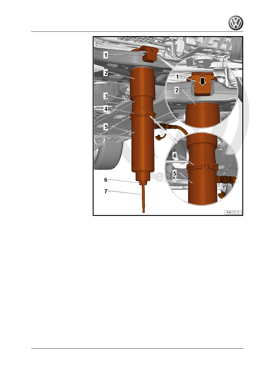
1 - Counter Hold - VAS6779/7-
2 - Funnel - VAS6779/6- , -arrow marking- on the Funnel -

VAS6779/6- must align in the center of both bolts -arrow-.
3 - Thrust Piece - VAS6779/9-
4 - Incremental Ring - VAS6779/8- , the marking -I- on the Incre‐

mental Ring - VAS6779/8- must align with the marking -X- on the

Thrust Piece - VAS6779/9-
5 - Hydraulic Press - VAS6178- with Bearing Installer - Wheel

Hub/Bearing Kit Pressure Head - T10205/13-
6 - Hexagon Nut - VAS6779/3-
7 - Threaded Rod - VAS6779/2-
– Press in both bonded rubber bushing at the same time.
– Remove Hydraulic Press - Bushing Tool Kit - VAS6779- from

the subframe and check seating of the pressed in bonded rub‐

ber bushing.

– Fasten the stabilizer bar with the subframe and the coupling

rod.

– Install the pendulum support. Refer to ⇒  Engine Mechanical,

Fuel Injection and Ignition; Rep. Gr.  10 ; Subframe Mount;

Pendulum Support, Removing and Installing or ⇒  Engine Me‐

chanical, Fuel Injection and Glow Plug; Rep. Gr.  10 ; Sub‐

frame Mount; Pendulum Support, Removing and Installing .

– Install the front noise insulation. Refer to ⇒  Body Exterior;

Rep. Gr.  66 ; Noise Insulation; Overview - Noise Insulation .

Tightening Specifications
♦ Refer to 

⇒ “2.1 Overview - Subframe”, page 16

♦ Refer to ⇒  Engine Mechanical, Fuel Injection and Ignition;

Rep. Gr.  10 ; Subframe Mount; Overview - Subframe Mount

or ⇒  Engine Mechanical, Fuel Injection and Glow Plug; Rep.

Gr.  10 ; Subframe Mount; Overview - Subframe Mount

♦ Refer to ⇒  Body Exterior; Rep. Gr.  66 ; Noise Insulation;

Overview - Noise Insulation .

2.7

Stabilizer Bar, Removing and Installing

Special tools and workshop equipment required
♦ Torque Wrench 1332 40-200Nm - VAG1332-
♦ Engine and Gearbox Jack - VAS6931-
Removing
– Loosen the wheel bolts.
– Raise the vehicle.
– Remove the wheels.
– Remove the lower noise insulation. Refer to ⇒  Body Exterior;

Rep. Gr.  66 ; Noise Insulation; Overview - Noise Insulation .

– Remove the exhaust system bracket from the subframe

-arrows-.

– Remove the pendulum support bolts -1-.

– Remove the hex nut -1- from the right and left coupling rod

-3-.

– Remove the coupling rod -3- from the stabilizer bar -2- on the

left and right sides.

– Remove the nuts -arrows- on the left and right side of the ve‐

hicle.

Vehicles with Level Control System Sensor
– Disconnect the connector -1- from the Left Front Level Control

System Sensor - G78- or  Right Front Level Control Sensor -

G289- .

– Remove the nut -1-.
– Remove the bracket -2- for the Left Front Level Control System

Sensor - G78- or  Right Front Level Control Sensor - G289-

from the control arm -3-.

– Remove the bolt -1-.
– Remove the Left Front Level Control System Sensor - G78-

-2- or Right Front Level Control Sensor - G289-

Continuation for all Vehicles.

– Remove the clips -1 and 2- for the wiring harness -3- from the

subframe and the steering gear.

– Remove the stabilizer bar bolts -1-.

– Remove the steering gear bolts -1-.
– Pry the steering gear out of the subframe alignment sleeves.


Content   ..  811  812  813  814   ..