Volkswagen Golf / Golf GTI / Golf Variant. Service manual - part 797


  Index      Volkswagen     Volkswagen Golf / Golf GTI / Golf Variant - service and repair manual 2013 year


Search            copyright infringement  


Content   ..  795  796  797  798   ..


Volkswagen Golf / Golf GTI / Golf Variant. Service manual - part 797


Removing
– Place sufficient lint-free cloths in the area of the engine and

transmission.

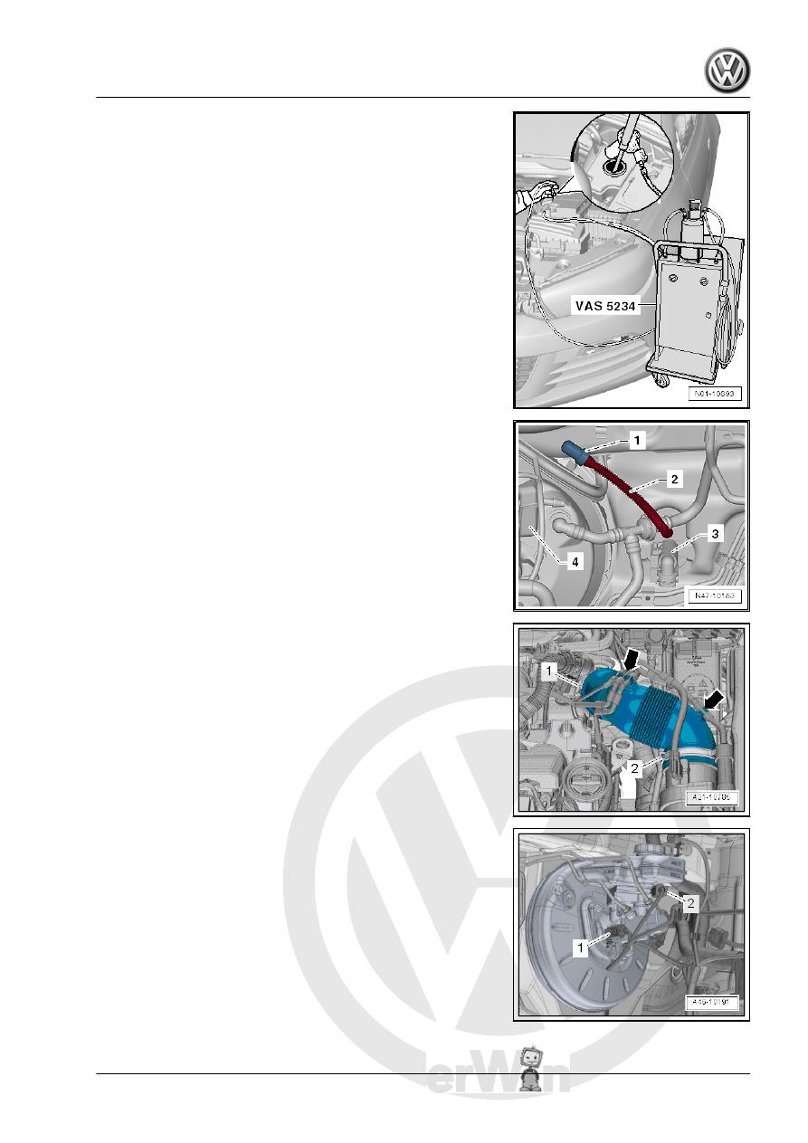
– Extract as much brake fluid as possible from the brake fluid

reservoir with the Brake Charger/Bleeder Unit - VAS5234- .

Vehicles with Manual Transmission
– Remove the supply hose -2- for the clutch master cylinder

-3- from the brake fluid reservoir -4-.

– Seal the supply hose -2- for the clutch master cylinder -3- using

Sealing Tool - T10249- -1- or Engine Bung Set - VAS6122- .

– Tie up the return hose -2-.

Vehicles with Diesel Engine and 2.0L Gasoline Engine
– Remove the engine cover. Refer to ⇒  Engine Mechanical,

Fuel Injection and Ignition; Rep. Gr.  10 ; Engine Cover; Engine

Cover, Removing and Installing . or ⇒  Engine Mechanical,

Fuel Injection and Glow Plug; Rep. Gr.  10 ; Engine Cover;

Engine Cover, Removing and Installing

– Loosen hose clamps and remove the air guide hose and air

filter housing. Refer to ⇒  Engine Mechanical, Fuel Injection

and Ignition; Rep. Gr.  24 ; Air Filter; Air Filter Housing, Re‐

moving and Installing .

Continuation for All Vehicles
– Release the connection -2- for the Brake Fluid Level Warning

Switch - F34- and remove.

– Release the left and right catches -2- in direction of -arrow-

and remove the brake fluid reservoir from the sealing plug

upward.

Note

Lightly push the brake line aside.

Installing
Install in reverse order of removal. Note the following:
– Make sure the sealing plugs are seated correctly in the brake

master cylinder -item 10- 

⇒ Item 10 (page 107)

 .

– Coat the plugs with brake fluid before pushing the brake fluid

reservoir into the master brake cylinder -item 10-

⇒ Item 10 (page 107)

 .

– Bleed the brake system. Refer to

⇒ “6.2 Hydraulic System, Standard Bleeding”, page 132

 .

Vehicles with Manual Transmission
– The seals -2- must be located in the return hose -1- to the

clutch master cylinder.

– Bleed the clutch mechanism. Refer to ⇒  Manual Transmis‐

sion; Rep. Gr.  30 ; Clutch Mechanism; Clutch Mechanism,

Bleeding .

Tightening Specification
♦ Refer to

⇒ “3.1 Overview - Brake Booster/Brake Master Cylinder”, page

106

♦ Refer to ⇒  Engine Mechanical, Fuel Injection and Glow Plug;

Rep. Gr.  23 ; Air Filter; Air Filter Housing, Removing and In‐

stalling

♦ Refer to ⇒  Engine Mechanical, Fuel Injection and Ignition;

Rep. Gr.  10 ; Engine Cover; Engine Cover, Removing and

Installing or ⇒  Engine Mechanical, Fuel Injection and Glow

Plug; Rep. Gr.  10 ; Engine Cover; Engine Cover, Removing

and Installing .

4

Vacuum System

⇒ “4.1 Overview - Vacuum Pump”, page 121
⇒ “4.2 Check Valve, Checking”, page 122
⇒ “4.3  Vacuum Sensor G608 , Removing and Installing”,

page 122
⇒ “4.4 Vacuum System, Checking”, page 123

4.1

Overview - Vacuum Pump

⇒ “4.1.1 Overview - Vacuum Pump, 2.0L Gasoline Engine”, page

121
⇒ “4.1.2 Brake Booster Vacuum Pump, Diesel Vehicles”,

page 121

4.1.1

Overview - Vacuum Pump, 2.0L Gasoline Engine

1 - Vacuum Hose

❑ Replace if damaged.

2 - Vacuum Line

❑ Replace if damaged.

3 - Seal

❑ Replace

4 - Vacuum Pump

❑ Refer to ⇒  Engine Me‐

chanical, Fuel Injection

and Ignition; Rep. Gr. 

15 ; Cylinder Head;

Overview - Cylinder

Head or ⇒  Engine Me‐

chanical, Fuel Injection

and Glow Plug; Rep.

Gr.  15 ; Cylinder Head;

Overview - Cylinder

Head .

5 - Bolt

❑ 9 Nm

4.1.2

Brake Booster Vacuum Pump, Diesel

Vehicles

The vacuum pump is installed behind the oil pump.

– Vacuum Pump/oil pump removing and installing. Refer to ⇒ 

Engine Mechanical, Fuel Injection and Ignition; Rep. Gr.  17 ;

Oil Pan/Oil Pump; Overview - Oil Pan/Oil Pump or⇒  Engine

Mechanical, Fuel Injection and Glow Plug; Rep. Gr.  17 ; Oil

Pan/Oil Pump; Overview - Oil Pan/Oil Pump .

4.2

Check Valve, Checking

– Blow some air first in one then in the other direction through

the check valve.

♦ The check valve -A- must allow air to flow through in the di‐

rection of the -arrow-.

♦ The check-valve must remain closed for opposite direction.
Observe correct installation position!

4.3

Vacuum Sensor - G608- , Removing

and Installing

The Vacuum Sensor - G608- -2- is only installed on some gaso‐

line engines.

Removing
– Disconnect the connector -1- from the Vacuum Sensor - G608-

-2-.

– Pull vacuum line out of brake booster.
– Unclip the Vacuum Sensor - G608- from the vacuum line.
Installing
Install in reverse order of removal. Note the following:


Content   ..  795  796  797  798   ..