Volkswagen Golf / Golf GTI / Golf Variant. Service manual - part 793


  Index      Volkswagen     Volkswagen Golf / Golf GTI / Golf Variant - service and repair manual 2013 year


Search            copyright infringement  


Content   ..  791  792  793  794   ..


Volkswagen Golf / Golf GTI / Golf Variant. Service manual - part 793


❑ Check for damage and correct seating

10 - Brake Carrier

❑ Supplied as an assembled replacement part with sufficient grease on guide pins
❑ If protective caps or guide pins are damaged use repair kit. Use supplied grease packet to lubricate guide

pins

2.2

Brake Caliper Piston, Removing and In‐

stalling

⇒ “2.2.1 Brake Caliper Piston, Removing and Installing”,

page 103
⇒ “2.2.2 Brake Caliper, Pre-Bleeding”, page 105

2.2.1

Brake Caliper Piston, Removing and In‐

stalling

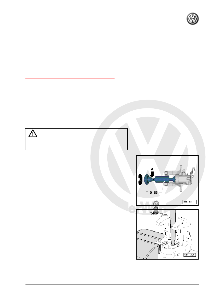
Special tools and workshop equipment required
♦ Brake Caliper Tool - T10165-
♦ Trim Removal Wedge - 3409-
Removing

WARNING

Adjust the brake piston is permitted only with the Brake Caliper

Tool - T10165- .

– Install the Brake Caliper Tool - T10165- so that the collar

touches the piston.

– Remove piston from brake caliper by turning knurled wheel

toward left.

– For pistons that are difficult to move, an open-end wrench (size

13 mm) can be applied at the appropriate wrench surface

-arrow A-.

– Remove the sealing ring using the Trim Removal Wedge -

3409- .

Installing
Install in reverse order of removal. Note the following:

Note

Install complete repair kit when servicing.

Only use mineral spirits to clean brake parts.

New brake calipers are filled with brake fluid and are pre-bled.

Apply thin coat of Assembly Paste - G 052 150 A2- to brake

cylinders, pistons and seals.

In case of repair, brake calipers must always be pre-bled be‐

fore being installed into vehicle (without brake pads). Refer to

⇒ “2.2.2 Brake Caliper, Pre-Bleeding”, page 105

 .

– Clean the surfaces on the pistons and seal only with mineral

spirits and then dry.

– Place the sealing ring in the groove.
– Apply a thin coat of Assembly Paste - G 052 150 A2- on the

piston and the seal before installing.

– Place the cap with the outer sealing lip on the piston.

– Insert inner sealing lip in cylinder groove with Trim Removal

Wedge - 3409- .

– Hold piston in front of brake caliper for this procedure.

– Install the pistons by turning clockwise.
– Be careful not to damage the cap.
– Use the Resetting & Extracting Tool - Plate - T10165/1- to help

you bolt it on.

– Install the Brake Caliper Tool - T10165- so that the collar on

the Resetting & Extracting Tool - Plate - T10165/1- is touching.

– Install by turning the thumbwheel on the Brake Caliper Tool -

T10165- clockwise.

The automatic adjustment in brake caliper is destroyed when pis‐

ton is moved with piston resetting tool (for example T 10145) or

foot brake is pressed.

2.2.2

Brake Caliper, Pre-Bleeding

– Open the bleeder valve -arrow A- and using a standard bleed‐

er bottle, fill with brake fluid until brake fluid with no bubbles

flows from the threaded hole (brake hose connection)

-arrow B-. Close the bleed valve.

Position brake caliper as shown during pre-bleed procedure.

3

Brake Booster/Brake Master Cylin‐

der

⇒ “3.1 Overview - Brake Booster/Brake Master Cylinder”,

page 106
⇒ “3.2 Brake Lamp Switch, Removing and Installing”, page 108
⇒ “3.3 Brake Master Cylinder, Removing and Installing”,

page 110
⇒ “3.4 Brake Booster, Removing and Installing”, page 113
⇒ “3.5 Brake Fluid Reservoir, Removing and Installing”,

page 118

3.1

Overview - Brake Booster/Brake Master Cylinder

WARNING

Only use new brake fluid conforming to VW standard (VW 501

14).

1 - Hex Nut

❑ 25 Nm
❑ Self-locking
❑ Replace after removing
❑ Tightening sequence.

Refer to

⇒ Fig. ““Tightening Se‐

quence”“ , page 108

2 - Bracket/Pedal Assembly

❑ Assembly sequence.

Refer to

⇒ “4.1 Overview - Brake

Pedal”, page 87

 .

❑ Mounting bracket, re‐

moving and installing.

Refer to

⇒ “4.5 Mounting Brack‐

et, Removing and Instal‐

ling”, page 90

 .

❑ Separate the brake ped‐

al from brake booster.

Refer to

⇒ “4.2 Brake Pedal, Re‐

moving from Brake

Booster”, page 88

 .

❑ Brake pedal to brake

booster, connecting.

Refer to

⇒ “4.3 Brake Pedal, At‐

taching to Brake Boos‐

ter”, page 89

 .

❑ Brake Pedal, removing

and installing. Refer to

⇒ “4.4 Brake Pedal, Re‐

moving and Installing”,

page 89

 .


Content   ..  791  792  793  794   ..