Volkswagen Golf / Golf GTI / Golf Variant. Service manual - part 775


  Index      Volkswagen     Volkswagen Golf / Golf GTI / Golf Variant - service and repair manual 2013 year


Search            copyright infringement  


Content   ..  773  774  775  776   ..


Volkswagen Golf / Golf GTI / Golf Variant. Service manual - part 775


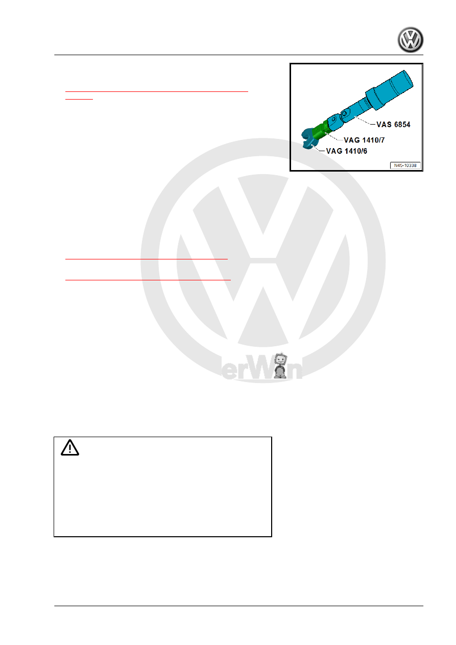
Special Tool Assembly for Tightening the Brake Lines
♦ Refer to

⇒ “3.1 Overview - Control Module and Hydraulic Unit”,

page 15

♦ Battery. Refer to ⇒  Electrical Equipment; Rep. Gr.  27 ; Bat‐

tery; Overview - Battery .

♦ Noise insulation bolts. Refer to ⇒  Body Exterior; Rep. Gr.  66 ;

Noise Insulation; Overview - Noise Insulation .

♦ Front exhaust pipe. Refer to ⇒  Rep. Gr.  26 ; Exhaust Pipes/

Mufflers; Front Exhaust Pipe, Removing and Installing .

♦ Pendulum support. Refer to ⇒  Engine Mechanical, Fuel In‐

jection and Ignition; Rep. Gr.  10 ; Subframe Mount; Overview

- Subframe Mount .

♦ Driveshaft. Refer to ⇒  Suspension, Wheels, Steering; Rep.

Gr.  40 ; Drive Axle; Overview - Drive Axle .

♦ Lower control arm. Refer to ⇒  Suspension, Wheels, Steering;

Rep. Gr.  40 ; Lower Control Arm and Ball Joint; Overview -

Lower Control Arm and Ball Joint .

♦ Front bleeder valve. Refer to

⇒ “1.1 Overview - Front Brake Caliper”, page 97

 .

♦ Rear bleeder valves. Refer to

⇒ “2.1 Overview - Rear Brake Caliper”, page 100

3.3

Control Module, Separating from Hy‐

draulic Unit

Special tools and workshop equipment required
♦ ESD Work Surface - VAS6613-
♦ TORX

®

 Insert T25

♦ If the ABS Control Module - J104- is faulty, then the control

module is to be separated from the ABS Hydraulic Unit - N55-

and only the control module replaced.

♦ If the ABS Hydraulic Unit - N55- is faulty, then replace the ABS

Hydraulic Unit - N55- together with the ABS Control Module -

J104- .

♦ To separate the ABS Control Module - J104- and the ABS Hy‐

draulic Unit - N55- the unit must be removed.

WARNING

♦ The return flow pump may also not be separated from the

ABS Hydraulic Unit - N55- .

♦ The circuit board is exposed when the ABS Control Mod‐

ule - J104- is removed.

♦ Protect the ABS Control Module - J104- from moisture and

dirt particles from getting inside.

♦ Avoid build-up of static electricity!

This build-up of static electricity can lead to malfunctions when

contacting electrical components.
– Touch a grounded object, before working on electrical equip‐

ment ESD Work Surface - VAS6613- . Do not touch directly

on the connector terminals or the electrical components.

– Place the ABS Hydraulic Unit - N55- with the ABS Control

Module - J104- on the ESD Work Surface - VAS6613- .

– Remove the three TORX

®

 bolts from the ABS Control Module

- J104- and set aside immediately (risk of confusing them with

the new TORX

®

 bolts).

– Place the ABS Hydraulic Unit - N55- with the ABS Control

Module - J104- upward on the ESD Work Surface - VAS6613- .

– Remove the ABS Control Module - J104- from the ABS Hy‐

draulic Unit - N55- without tilting it.

– Cover ABS Control Module - J104- solenoid coils with a lint-

free cloth.

– Clean the ABS Hydraulic Unit - N55- sealing surface using

mineral spirits and a lint-free cloth.

The ABS Hydraulic Unit - N55- sealing surface must not be

worked with a file, metal scraper, sand paper or similar.
If the ABS Hydraulic Unit - N55- sealing surface is damaged (for

example through grooves or scrapes) the ABS Hydraulic Unit -

N55- must be replaced with the ABS Control Module - J104- .
The seal on the ABS Control Module - J104- must not be pulled

out or raised up.
The seal on the ABS Control Module - J104- cannot be replaced.

3.4

Control Module, Attaching to Hydraulic

Unit

Special tools and workshop equipment required
♦ Torque Screwdriver - VAG1624-
♦ ESD Work Surface - VAS6613-
♦ TORX

®

 insert T25

WARNING

Excessive shaking (for example, dropping, impact) can dam‐

age the ABS Control Module - J104- . Do not use the ABS

Control Module - J104- again if this happens.

• Surface must be cleaned before assembling.
– Place the ABS Control Module - J104- on the ABS Hydraulic

Unit - N55- without tilting it.

– Tighten the ABS Hydraulic Unit - N55- and the ABS Control

Module - J104- with the supplied new TORX

®

 bolts in two

steps switching back and forth to the tightening specification.

Note

The ABS Hydraulic Unit - N55- threads cannot be re-cut to

secure the ABS Control Module - J104- .

If the threads are damaged, the ABS Hydraulic Unit - N55-

must be replaced.

If the bolts are difficult to remove by hand or cannot be tight‐

ened to the tightening specification then the threads are dam‐

aged.

Tightening Specification
♦ Refer to

⇒ “3.1 Overview - Control Module and Hydraulic Unit”,

page 15

Note

A new ABS Control Module - J104- can be installed on an old

ABS Hydraulic Unit - N55- three times, maximum. This as‐

sures the elastic seal will not leak.

A used ABS Control Module - J104- may not be installed a

second time.

3.5

Brake Lines, Attaching to Hydraulic Unit

On Tandem Master Brake Cylinder:
A - Master Brake Cylinder Primary Piston Circuit to the ABS Hy‐

draulic Unit - N55- .
- Identification: 6 mm diameter and tube fitting with a M12 x 1

thread
B - Master Brake Cylinder Secondary Piston Circuit to the ABS

Hydraulic Unit - N55- .
- Identification: 6 mm diameter and tube fitting with a M12 x 1

thread
1 - ABS Hydraulic Unit - N55- to the Left Front Brake Caliper
3 - ABS Hydraulic Unit - N55- to the Left Rear Brake Caliper
4 - ABS Hydraulic Unit - N55- to the Right Rear Brake Caliper

Tightening Sequence:
1 - ABS Hydraulic Unit - N55- to the Right Rear Brake Caliper
- Identification: 5.25 mm diameter and tube fitting with a M12 x 1

short thread
2 - ABS Hydraulic Unit - N55- to the Left Front Brake Caliper
- Identification: 5.25 mm diameter and tube fitting with a M10 x 1

thread
3 - ABS Hydraulic Unit - N55- to the Right Front Brake Caliper
- Identification: 5.25 mm diameter and tube fitting with a M12 x 1

short thread
4 - ABS Hydraulic Unit - N55- to the Left Rear Brake Caliper
- Identification: 5.25 mm diameter and tube fitting with a M10 x 1

thread
5 - ABS Hydraulic Unit - N55- to the Master Brake Cylinder Sec‐

ondary Piston Circuit
- Identification: 6 mm diameter and tube fitting with a M12 x 1

thread
6 - ABS Hydraulic Unit - N55- to the Master Brake Cylinder Pri‐

mary Piston Circuit
- Identification: 6 mm diameter and tube fitting with a M12 x 1

thread
Tightening Specification
♦ Refer to

⇒ “3.1 Overview - Control Module and Hydraulic Unit”,

page 15


Content   ..  773  774  775  776   ..