Volkswagen Golf / Golf GTI / Golf Variant. Service manual - part 716
4.2
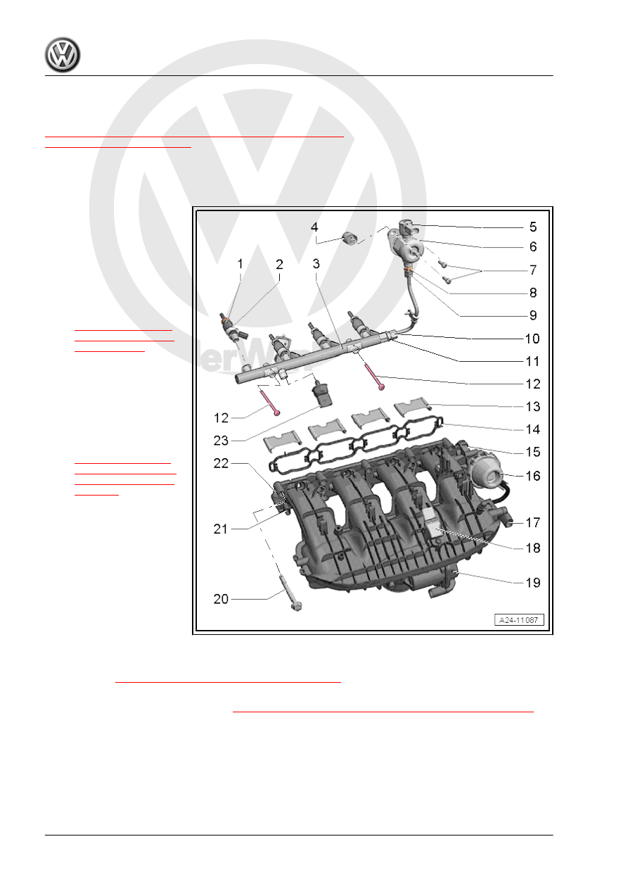
Overview - Intake Manifold Lower Sec‐
tion with Fuel Rail
⇒ “4.2.1 Overview - Intake Manifold Lower Section with Fuel Rail,
Direct Fuel Injection”, page 300
4.2.1
Overview - Intake Manifold Lower Section with Fuel Rail, Direct Fuel Injec‐
tion
1 - Fuel Injector
❑ With combustion cham‐
ber seal (Teflon
®
seal),
always replace
❑ Replace the O-rings.
❑ Make sure it is installed
in the correct position.
❑ Removing and instal‐
ling. Refer to
2 - Support Ring
❑ Replace after removing
3 - Fuel Rail for Combustion
Chamber Fuel Injector
❑ 9 Nm
❑ Removing and instal‐
ling. Refer to
4 - Roller Tappet
5 - Fuel Pressure Regulator
Valve - N276-
6 - High Pressure Pump
❑ With Fuel Pressure
Regulator Valve - N276-
❑ There is an electric fuel
pump located in the fuel
tank that supplies the
fuel to the mechanical
high pressure pump.
❑ Pay attention when installing the high pressure pump, that no dirt enters the fuel system.
❑ The fuel system must be without pressure to install the high-pressure pump, releasing fuel pressure.
Refer to
⇒ “1.2 High Fuel Pressure, Reducing”, page 283
❑ Install the fuel lines free of tension
❑ Removing and installing. Refer to
⇒ “7.2 High Pressure Pump, Removing and Installing”, page 328
.
7 - High Pressure Pump Bolts
❑ 20 Nm
❑ Replace after removing
❑ Tighten uniformly
8 - High Pressure Line Connection On High Pressure Pump
9 - High Pressure Line Union Nut
❑ 27 Nm