Volkswagen Golf / Golf GTI / Golf Variant. Service manual - part 713


  Index      Volkswagen     Volkswagen Golf / Golf GTI / Golf Variant - service and repair manual 2013 year


Search            copyright infringement  


Content   ..  711  712  713  714   ..


Volkswagen Golf / Golf GTI / Golf Variant. Service manual - part 713


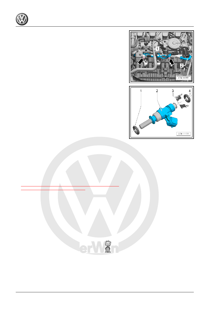
– Remove bolts -arrows- from the fuel rail.
– Carefully remove the fuel rail and fuel injector upward.
– Disconnect the connectors on the fuel injectors.

Overview - Fuel Injector
1 - Replace the O-ring (lightly coat with clean engine oil during

installation)
2 - Fuel Injector
3 - Clip
4 - Replace the O-ring (lightly coat with clean engine oil during

installation)
Installing
– Replace the O-ring on the fuel injector.
– Coat the O-rings with clean engine oil before installing.
– Connect the connectors on the fuel injectors.
– Press the fuel rail and the fuel injector by hand all the way into

the opening for the intake manifold (oil and grease free).

– Install in reverse order of removal.
– Install the fuel rail.
Tightening Specifications
♦ Refer to

⇒ “4.2.2 Overview - Intake Manifold Lower Section with Fuel

Rail, Multiport Fuel Injection”, page 302

2.4

Fuel Injector Seals, Replacing

Special tools and workshop equipment required
♦ Injector/Combustion Chamber Seal Tool Set - Puller -

T10133/2A-

♦ Injector/Combustion Chamber Seal Tool Set - Sliding Hammer

- T10133/3-

♦ Injector/Combustion Chamber Seal Tool Set - Nylon Brush -

T10133/4-

♦ Injector/Combustion Chamber Seal Tool Set - Assembly Cone

- T10133/5-

♦ Injector/Combustion Chamber Seal Tool Set - Assembly

Sleeve - T10133/6-

♦ Injector/Combustion Chamber Seal Tool Set - Assembly Cal‐

ibration Sleeve - T10133/7- njector/Combustion Chamber

Seal Tool Set - Assembly Calibration Sleeve - T10133/8-

Caution

This procedure contains mandatory replaceable parts. Refer

to component overview prior to starting procedure.

Mandatory Replacement Parts
♦ Mount - Fuel Injector
♦ O-ring - Fuel Injector
♦ Ring - Intermediate Fuel Injector
♦ Ring - Sealing Combustion Chamber
♦ Ring - Spacer
♦ Ring - Support

Note

The combustion chamber seal (Teflon

®

 seal) must always be re‐

placed before reinstalling the fuel injector.

– Remove the combustion chamber seal -3- with the appropriate

tool (for example with cut the seal open with a razor and spread

seal open with a small screwdriver and pull it forward and off.)

When doing this, make sure not to damage the groove and

circumferential rib in the groove base.

Note

If the groove was damaged, the fuel injector must be replaced.

– Clean off any combustion residue on the seal groove and on

the shaft of the fuel injector with a clean cloth before installing

the new combustion chamber seal.

– Place the Injector/Combustion Chamber Seal Tool Set As‐

sembly Cone - T10133/5- with a new combustion chamber

seal -1- onto the fuel injector -2-.

– Slide the combustion chamber seal with the Injector/Combus‐

tion Chamber Seal Tool Set Assembly Sleeve - T10133/6-

onto the Injector/Combustion Chamber Seal Tool Set Assem‐

bly Cone - T10133/5- as far as possible.

– Rotate the Injector/Combustion Chamber Seal Tool Set As‐

sembly Sleeve - T10133/6- and slide the combustion chamber

seal all the way onto the Injector/Combustion Chamber Seal

Tool Set Assembly Cone - T10133/5- .

– Remove the Injector/Combustion Chamber Seal Tool Set -

Assembly Cone - T10133/5- . Slide the combustion chamber

seal to the seal groove using the Injector/Combustion Cham‐

ber Seal Tool Set Assembly Sleeve - T10133/6- .

– Press the Calibration Sleeve - T10133/7- with a gentle turning

movement (approximately 180°) all the way onto the fuel in‐

jector.

– Pull off Calibration Sleeve - T10133/7- again using turning

motion in opposite direction.

– Press the Calibration Sleeve - T10133/8- with a gentle turning

movement (approximately 180°) all the way onto the fuel in‐

jector.

– Pull off Calibration Sleeve - T10133/8- again using turning

motion in opposite direction.

– Replace the O-ring on the fuel injector and coat with clean oil

before installing.

– Use the included Injector/Combustion Chamber Seal Tool Set

Nylon Brush - T10133/4- to thoroughly clean the high-pressure

fuel injector bores in the cylinder head before installing the fuel

injectors.

Note

Do not oil or grease the combustion chamber sealing ring on

the fuel injector.

When installing the injector valve, make sure there is no clean‐

ing product or oil in the holes in the cylinder head.

– Press fuel injector by hand into cylinder head (free of oil and

grease) as far as stop. Make sure the fuel injectors are posi‐

tioned correctly inside the cylinder head.

– The tab -1- and the opening -arrow- must be on top of each

other in the cylinder head.

Note

The fuel injector must not be difficult to install. If necessary,

wait as the combustion chamber seal continues to pull itself

together.

Make sure the fuel injectors are installed securely in the cyl‐

inder head.

If it is difficult to install the fuel injector by hand, use the Injec‐

tor/Combustion Chamber Seal Tool Set - Puller - T10133/2A-

-2- with the Sliding Hammer - T10133/3- to guide in the fuel

injector.

– Coat the fuel injectors O-rings with clean engine oil so they are

easier to guide into the fuel rail.

– Install the fuel rail. Refer to

⇒ “4.4 Fuel Rail, Removing and Installing, Direct Fuel Injec‐

tion”, page 309

 .

– Install the intake manifold. Refer to

⇒ “4.3 Intake Manifold, Removing and Installing”, page 304

 .

2.5

Fuel Injectors, Cleaning

Special tools and workshop equipment required
♦ Ultrasonic Cleaning Unit - VAS6418-
♦ Mounting Plate for Injection Modules - VAS6418/1-
♦ Cleaning Fluid - VAS6418/2-


Content   ..  711  712  713  714   ..