Volkswagen Golf / Golf GTI / Golf Variant. Service manual - part 690


  Index      Volkswagen     Volkswagen Golf / Golf GTI / Golf Variant - service and repair manual 2013 year


Search            copyright infringement  


Content   ..  688  689  690  691   ..


Volkswagen Golf / Golf GTI / Golf Variant. Service manual - part 690


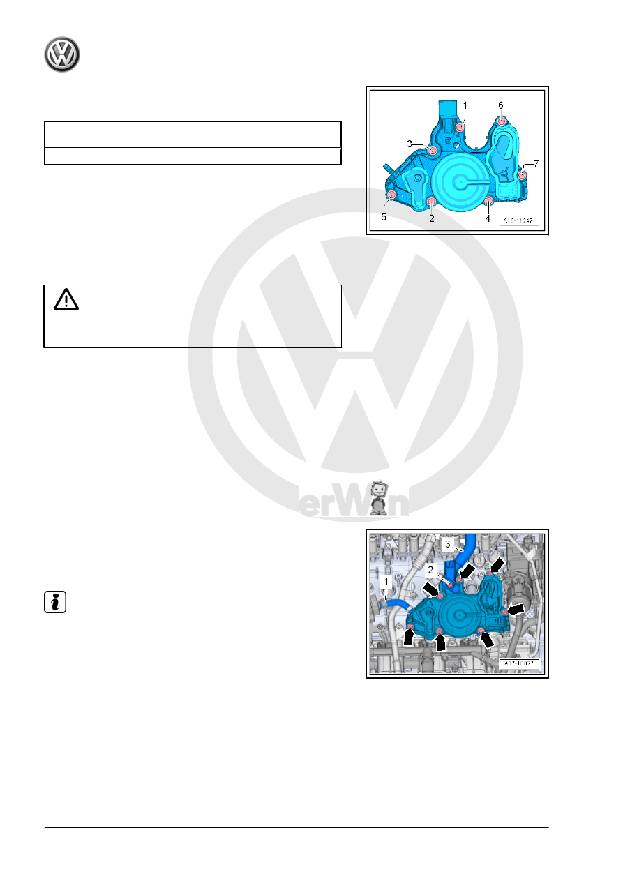
Oil Separator - Tightening Sequence
– Tighten the bolts in the sequence -1 through 7-.

Bolts

Tightening Sequence and Tor‐

que Specification

-1 through 7-

9 Nm.

3.2

Oil Separator, Removing and Installing

Removing

Caution

This procedure contains mandatory replaceable parts. Refer

to component overview prior to starting procedure.

Mandatory Replacement Parts
♦ Seal - Oil Separator
♦ Seals - Oil Separator to Crankcase Hose
– Disconnect the ignition coil sensors connectors and remove

them from the ignition coils at the same time.

– Remove the ignition coils bolts “3, 4”, and remove the ignition

coils.

– Loosen the hose clamp -1- and remove the hose from EVAP

Canister Purge Regulator Valve 1 - N80- .

– Remove bolt -2- and then remove crankcase ventilation hose

-3- from oil separator.

– Remove the bolts -arrows- and the oil separator.
Installing
Install in reverse order of removal. Note the following:

Note

Always replace gasket and seals.

Secure hose connections with standard production clamps.

Refer to the Parts Catalog.

Tightening Specifications
♦ Refer to

⇒ “3.1 Overview - Crankcase Ventilation”, page 195

 .

Pro

te

c

t

ed

  b

y

  co

p

y

rig

h

t. 

C

o

p

y

in

g

  fo

pr

iv

a

t

e

 o

r

 c

o

m

m

e

r

c

ia

p

u

rp

o

s

e

s

,

 i

n

 p

a

rt

o

r i

n

 w

h

o

le

is

 n

o

t

 p

e

r

m

it

t

e

d

 u

n

l

e

s

s

 a

ut

ho

r

i

s

ed

 b

y

 V

olk

sw

a

ge

n AG

.


V

olk

s

w

a

g

en

 AG do

es 

n

ot g

uar

ante

e

 or a

c

c

ep

t

 a

ny


li

a

b

i

li

t

y

 w

ith

 r

e

s

p

e

c

t

 t

o


th

e

 c

o

rr

e

c

t

n

e

s

s


o

f

in

fo

r

m

a

tio

n

 in

 th

is

 d

o

c

um

en

t.

C

o

py

rig

ht b

y


V

olk

sw

a

ge

n


A

G.

4

Oil Filter/Oil Pressure Switch

⇒ “4.1 Overview - Oil Filter”, page 197

 .

⇒ “4.2 Overview - Oil Pressure Switch/Oil Pressure Regulator

Valve”, page 198

 .

⇒ “4.3  Oil Pressure Switch F1 , Removing and Installing”,

page 199

 .

⇒ “4.4  Reduced Oil Pressure Switch F378 , Removing and In‐

stalling”, page 200

 .

⇒ “4.5  Oil Pressure Switch, Level 3 F447 , Removing and Instal‐

ling”, page 201

 .

⇒ “4.6 Oil Pressure, Checking”, page 202

 .

4.1

Overview - Oil Filter

1 - Auxiliary Components

Bracket

❑ Removing and instal‐

ling. Refer to

⇒ “1.5 Auxiliary Compo‐

nents Bracket, Remov‐

ing and Installing”, page

53

 .

2 - Seal

❑ Replace after removing

3 - Oil Filter

❑ Removing and instal‐

ling. Refer to ⇒ Mainte‐

nance ; Booklet  36.1 ;

Procedure Descriptions;

Engine Oil, Draining,

Replacing Oil Filter, and

Filling .

4 - O-Ring

❑ Replace after removing
❑ Coat with engine oil

5 - Oil Filter Housing

❑ 25 Nm

6 - Oil Drain Supports
7 - O-Rings

❑ No replacement part,

part of the valve unit de‐

livery package -item 6-

⇒ Item 6 (page 197)

 .

8 - Bolt

❑ Tightening specification

and sequence. Refer to

⇒ Fig. ““Accessory As‐

sembly Bracket - Tightening Specifications and Tightening Sequence”“ , page 45

 .

4.2

Overview - Oil Pressure Switch/Oil Pressure Regulator Valve

1 - Bolt

❑ 4 Nm + 90° turn
❑ Replace after removing

2 - Oil Pressure Regulation

Valve - N428-

❑ Checking. Refer to Ve‐

hicle Diagnostic Tester

❑ Removing and instal‐

ling. Refer to

⇒ “4.8  Oil Pressure

Regulation Valve N428 ,

Removing and Instal‐

ling”, page 206

 .

3 - O-Ring

❑ Replace after removing
❑ Coat with engine oil

4 - O-Rings

❑ Replace after removing
❑ Coat with engine oil

5 - Bolt

❑ 4 Nm + 45° turn
❑ Replace after removing

6 - Piston Cooling Nozzle Con‐

trol Valve - N522-

❑ Checking. Refer to Ve‐

hicle Diagnostic Tester

❑ Removing and instal‐

ling. Refer to

⇒ “4.7  Piston Cooling

Nozzle Control Valve

N522 , Removing and

Installing”, page 205

 .

7 - Seal

❑ Replace oil pressure switch after each time it is loosened

8 - Oil Pressure Switch - F1-

❑ 20 Nm
❑ Blue or gray insulation
❑ Checking. Refer to Vehicle Diagnostic Tester
❑ Removing and installing. Refer to

⇒ “4.3  Oil Pressure Switch F1 , Removing and Installing”, page 199

 .

9 - Reduced Oil Pressure Switch - F378-

❑ 20 Nm
❑ Brown insulation
❑ Checking. Refer to Vehicle Diagnostic Tester
❑ Removing and installing. Refer to

⇒ “4.4  Reduced Oil Pressure Switch F378 , Removing and Installing”, page 200

 .

10 - Seal

❑ Replace oil pressure switch after each time it is loosened

11 - Seal

❑ Replace oil pressure switch after each time it is loosened

12 - Oil Pressure Switch, Level 3 - F447-

❑ 20 Nm
❑ Checking. Refer to Vehicle Diagnostic Tester
❑ Removing and installing. Refer to

⇒ “4.5  Oil Pressure Switch, Level 3 F447 , Removing and Installing”, page 201

 .

❑ Installed position. Refer to 

⇒ Fig. ““ Oil Pressure Switch, Level 3 -F447- Installed Position”“ , page 199

Oil Pressure Switch, Level 3 - F447- Installed Position

4.3

Oil Pressure Switch - F1- , Removing

and Installing

Special tools and workshop equipment required
♦ Socket and Jointed Extension - 24mm - T40175-

Caution

This procedure contains mandatory replaceable parts. Refer

to component overview prior to starting procedure.

Mandatory Replacement Parts
♦ Seal - Oil Pressure Switch
Removing

Note

Place a cloth under the accessory assembly bracket to collect

leaking engine oil.

Replace the seal after each time the oil pressure switch is

loosened.

– Disconnect the connector -arrow- from the Oil Pressure Switch

- F1- .


Content   ..  688  689  690  691   ..