Volkswagen Golf / Golf GTI / Golf Variant. Service manual - part 678


  Index      Volkswagen     Volkswagen Golf / Golf GTI / Golf Variant - service and repair manual 2013 year


Search            copyright infringement  


Content   ..  676  677  678  679   ..


Volkswagen Golf / Golf GTI / Golf Variant. Service manual - part 678


Note

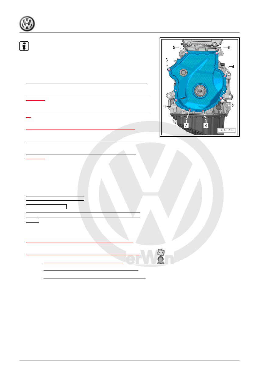
Tighten the bolts -1 and 4- with an additional turn after installing

the vibration damper. The bolts must be removed again to install

the vibration damper.

– Install the vibration damper. Refer to

⇒ “1.4 Vibration Damper, Removing and Installing”, page 47

 .

– Install the upper timing chain cover. Refer to

⇒ “2.2.1 Upper Timing Chain Cover, Removing and Installing”,

page 106

 .

– Install the ribbed belt tensioning damper. Refer to

⇒ “1.3 Ribbed Belt Tensioner, Removing and Installing”, page

47

 .

– Install the ribbed belt. Refer to

⇒ “1.2 Ribbed Belt, Removing and Installing”, page 46

 .

– Install the vacuum pump. Refer to

⇒ “1.4 Vacuum Pump, Removing and Installing”, page 100

 .

– Install the high pressure pump. Refer to

⇒ “7.2 High Pressure Pump, Removing and Installing”,

page 328

 .

The rest of the installation is performed in reverse order of re‐

moval, noting the following:
– After performing work on the chain drive the adaptation value

in the Engine Control Module (ECM) must be adapted. To do

this turn on the ignition and select the following menu items on

the Vehicle Diagnostic Tester :

01 - Engine Electronics

Guided Functions

01 - Adaptation After Repair Work on the Chain

Drive

Tightening Specifications
♦ Refer to

⇒ “3.1 Overview - Camshaft Timing Chain”, page 114

 .

♦ Refer to

⇒ “3.2 Overview - Balance Shaft Drive Chain”, page 116

 .

♦ Refer to 

⇒ “4.1 Overview - Valvetrain”, page 133

 .

♦ Refer to 

⇒ “3.1 Overview - Air Filter Housing”, page 293

 .

♦ Refer to 

⇒ “7.1 Overview - High Pressure Pump”, page 325

 .

♦ Refer to ⇒  Body Exterior; Rep. Gr.  66 ; Noise Insulation;

Overview - Noise Insulation .

4.2.2

Camshaft, Removing and Installing, En‐

gine Codes CNTA, CXCA, CXCB

Special tools and workshop equipment required
♦ Central Valve Assembly Tool - T10352-
♦ Counterhold - Vibration Damper - T10355-
♦ Chain Tensioner Lever - T40243-
♦ Tensioner Locking Tool - T40267-

♦ Camshaft Locks - T40271-
♦ Adapter - T40266-
♦ Sealant - D 154 103 A1-
Removing

Note

The sealing surfaces of the lower cylinder head cover and on

the upper cylinder head must not be reworked.

The camshaft bearings are integrated in the cylinder head or

cylinder head cover. Before removing the cylinder head cover,

release the tension on the camshaft timing chain.

When installing, secure all cable ties back to same positions.

– Remove the air filter housing. Refer to

⇒ “3.2 Air Filter Housing, Removing and Installing”,

page 294

 .

– Remove the upper coolant pipe. Refer to

⇒ “3.3 Upper Coolant Pipes, Removing and Installing”,

page 242

 .

– Remove the ignition coils. Refer to

⇒ “1.3 Ignition Coils with Power Output Stages, Removing and

Installing”, page 357

 .

– Disconnect the connectors:
1 - For Turbocharger Recirculation Valve - N249-
2 - For Camshaft Position Sensor 3 - G300-
3 - For Fuel Pressure Regulator Valve - N276-
– Disconnect the connectors -arrows- from the cam adjustment

actuator.

– Remove the bolt -5- and free up the ground cable.
– Free up the connector from the clip -4- and pivot it forward.
– Release the retainers in direction of -arrow-, remove the wiring

duct upward from the bracket and move it towards the front.

NOTICE

Risk of destroying the coolant pipes through deformation.
– Never change the coolant pipe bent shape.

– Remove bolts -1, 2 and 3-. Carefully swing coolant line back‐

ward slightly.

– Disconnect the connector -1- from the EVAP Canister Purge

Regulator Valve 1 - N80- .

– Press the release button on the crankcase ventilation hose

-2- and remove the hose.

– Remove the bolts -arrows- and the crankcase ventilation.
– Remove the high pressure pump. Refer to

⇒ “7.2 High Pressure Pump, Removing and Installing”,

page 328

 .

– Remove the vacuum pump. Refer to

⇒ “1.4 Vacuum Pump, Removing and Installing”, page 100

 .

– Support the engine in its installed position. Refer to

⇒ “2.5 Engine, Supporting in Installed Position”, page 33

 .

– Remove the engine bracket. Refer to

⇒ “2.2 Engine Mount, Removing and Installing”, page 30

 .

– Remove the noise insulation. Refer to ⇒  Body Exterior; Rep.

Gr.  66 ; Noise Insulation; Overview - Noise Insulation .

– Remove the right wheel housing liner front section. Refer to ⇒ 

Body Exterior; Rep. Gr.  66 ; Wheel Housing Liner; Front

Wheel Housing Liner, Removing and Installing .

– Remove engine support. Refer to

⇒ “1.6 Engine Support, Removing and Installing”, page 55

 .

– Remove timing chain upper cover. Refer to

⇒ “2.2.1 Upper Timing Chain Cover, Removing and Installing”,

page 106

 .

– Turn the vibration damper with the Counterhold - Vibration

Damper - T10355- to the “TDC point”.

• The markings -1- on the camshaft chain sprockets must be

opposite the markings -2 and 3-.

• The notch on the vibration damper and the marking on the

lower cover for timing chain -arrow- must be opposite one an‐

other.

– Remove the lower timing chain cover. Refer to

⇒ “2.2.2 Lower Timing Chain Cover, Removing and Installing”,

page 108

 .

Note

The pilot valve has left-hand threads.

– Remove the left and right pilot valves using the Assembly Tool

- T10352/2- in the direction of -arrow-.

– Remove the bolts -arrows- and remove the bearing bracket.

– Remove the bolts -arrows-.

– Install the Chain Tensioner Lever - T40243- -arrows-.
– Press the chain tensioner locking ring -1- together and hold it.
– Slowly press and hold the Chain Tensioner Lever - T40243-

in the direction of -arrow-.

– Secure the chain tensioner with the Tensioner Locking Tool -

T40267- .

– Remove the Chain Tensioner Lever - T40243- .


Content   ..  676  677  678  679   ..