Volkswagen Golf / Golf GTI / Golf Variant. Service manual - part 667
2
Timing Chain Cover
⇒ “2.1 Overview - Timing Chain Cover”, page 104
⇒ “2.2 Timing Chain Cover, Removing and Installing”,
page 106
⇒ “2.3 Vibration Damper Sealing Ring, Replacing”, page 112
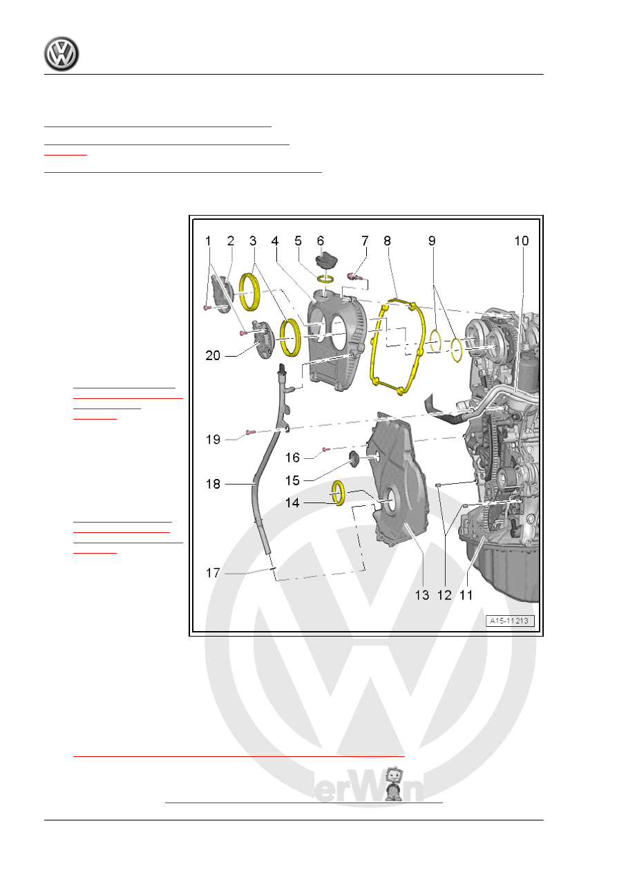
2.1
Overview - Timing Chain Cover
1 - Bolt
❑ 4 Nm + 45°
❑ Replace after removing
2 - Exhaust Camshaft Adjust‐
ment Valve 1 - N318-
3 - Seals
❑ To replace the cover
must be removed.
4 - Timing Chain Cover Upper
Section
❑ Removing and instal‐
ling. Refer to
5 - Seal
❑ Replace if damaged
6 - Cover
7 - Bolt
❑ Tightening sequence.
Refer to
8 - Seal
❑ Replace if damaged
9 - O-Ring
❑ Replace after removing
❑ Coat with engine oil
10 - Not Installed
11 - Engine
12 - Alignment Pins
❑ Centering the cover
13 - Lower Timing Chain Cover
❑ With seal
❑ Replace after removing. Refer to
⇒ “2.2.2 Lower Timing Chain Cover, Removing and Installing”, page 108
14 - Shaft Seal
❑ For the vibration damper
❑ Replacing. Refer to