Volkswagen Golf / Golf GTI / Golf Variant. Service manual - part 664


  Index      Volkswagen     Volkswagen Golf / Golf GTI / Golf Variant - service and repair manual 2013 year


Search            copyright infringement  


Content   ..  662  663  664  665   ..


Volkswagen Golf / Golf GTI / Golf Variant. Service manual - part 664


14 - O-Ring

❑ Coat with coolant
❑ Replace after removing

15 - Connection

❑ For coolant hose

16 - Bolt

❑ 9 Nm

17 - Mount

❑ For engine cover

18 - Engine Lifting Eye
19 - Bolt

❑ 8 Nm + 90° turn
❑ Replace after removing

20 - Partition Plate
21 - Ball Pin

❑ For engine cover

22 - Engine Lifting Eye
23 - Bolt

❑ 8 Nm + 90° turn
❑ Replace after removing

24 - Alignment Pin

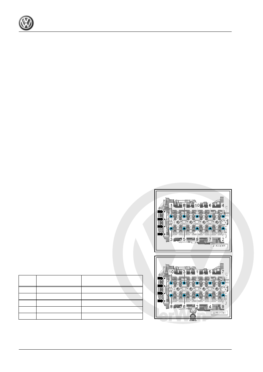
Loosening Cylinder Head
– Remove the bolts -arrows-.
– Loosen the cylinder head bolts in the sequence -1 to 10-.

Cylinder Head Tightening Sequence
– Tighten the cylinder head bolts in the sequence -1 to 10- as

follows.

Step

Bolts

Tightening Specification/Addi‐

tional Turn

1.

-1- through -10-

40 Nm

2.

-1- through -10-

Turn an additional 90°.

3.

-1- through -10-

Turn an additional 90°.

4.

Bolts -arrows-

4 Nm

5.

Bolts -arrows-

Turn an additional 90°.

Checking Cylinder Head for Distortion
– Check the cylinder head at several locations for distortion us‐

ing a Straight Edge - 500mm - VAS6075- and a feeler gauge.

♦ Maximum permissible distortion: 0.05 mm

1.2

Overview - Camshaft Housing

1 - Cylinder Head
2 - O-Ring

❑ Only installed on vehi‐

cles with the engine co‐

des CNTA, CXCA,

CXCB

❑ Replace after removing
❑ Coat with engine oil

3 - Cam Adjustment Actuator

❑ Only installed on vehi‐

cles with the engine co‐

des CNTA, CXCA,

CXCB

4 - Bolt

❑ 5 Nm
❑ Only installed on vehi‐

cles with the engine co‐

des CNTA, CXCA,

CXCB

5 - Ball Pin

❑ 9 Nm
❑ For engine cover

6 - O-Ring

❑ Replace after removing
❑ Coat with engine oil

7 - Plug
8 - O-Ring

❑ Replace after removing
❑ Coat with engine oil

9 - Camshaft Position Sensor

3 - G300-

❑ Overview. Refer to 

⇒ “1.1 Overview - Ignition System”, page 356

 .

10 - Bolt

❑ Tightening specification. Refer to 

⇒ “1.1 Overview - Ignition System”, page 356

 .

11 - Oil Separator

❑ Removing and installing. Refer to 

⇒ “3.2 Oil Separator, Removing and Installing”, page 196

 .

Pro

te

c

t

ed

  b

y

  co

p

y

rig

h

t. 

C

o

p

y

in

g

  fo

pr

iv

a

t

e

 o

r

 c

o

m

m

e

r

c

ia

p

u

rp

o

s

e

s

,

 i

n

 p

a

rt

o

r i

n

 w

h

o

le

is

 n

o

t

 p

e

r

m

it

t

e

d

 u

n

l

e

s

s

 a

ut

ho

r

i

s

ed

 b

y

 V

olk

sw

a

ge

n AG

.


V

olk

s

w

a

g

en

 AG do

es 

n

ot g

uar

ante

e

 or a

c

c

ep

t

 a

ny


li

a

b

i

li

t

y

 w

ith

 r

e

s

p

e

c

t

 t

o


th

e

 c

o

rr

e

c

t

n

e

s

s


o

f

in

fo

r

m

a

tio

n

 in

 th

is

 d

o

c

um

en

t.

C

o

py

rig

ht b

y


V

olk

sw

a

ge

n


A

G.

12 - Bolt

❑ Tightening specification and sequence. Refer to

⇒ Fig. ““Vacuum Pump - Tightening Specifications”“ , page 94

 .

13 - Seal

❑ Replace after removing

14 - Vacuum Pump

❑ Removing and installing. Refer to 

⇒ “1.4 Vacuum Pump, Removing and Installing”, page 100

 .

15 - Bolt

❑ Tightening specification. Refer to 

⇒ Fig. ““Vacuum Pump - Tightening Specifications”“ , page 94

 .

16 - Seal

❑ Replace after removing

17 - O-Ring

❑ Replace after removing
❑ Coat with engine oil

18 - Camshaft Position Sensor - G40-

❑ Overview. Refer to 

⇒ “1.1 Overview - Ignition System”, page 356

 .

19 - Bolt

❑ Tightening specification. Refer to 

⇒ “1.1 Overview - Ignition System”, page 356

 .

20 - Bolt

❑ 9 Nm

21 - Bracket

❑ For EVAP Canister Purge Regulator Valve 1 - N80-

Vacuum Pump - Tightening Specifications
Tighten with a new bolts as follows:

Step

Bolts

Tightening Specification/Additional

Turn

1.

-1- through -3-

Install hand-tight

2.

-1- through -3-

8 Nm

3.

-1- through -3-

180° additional turn

1.3

Cylinder Head, Removing and Installing

Special tools and workshop equipment required
♦ Engine Bung Set - VAS6122-
♦ Engine Support Bridge - 10-222A-
Removing

Caution

This procedure contains mandatory replaceable parts. Refer

to component overview prior to starting procedure.

Mandatory Replacement Parts
♦ Nuts - Turbocharger to Engine

♦ Seal - Turbocharger to Engine
♦ Bolts - Cylinder Head
♦ Gasket - Cylinder Head

Note

Before installing the cylinder head the engine support and the

engine mount are temporarily re-installed because the eyes

from the engine support bridge are secure on the cylinder

head.

When installing, secure all cable ties back to the same posi‐

tions.

Close the open channels from the intake and exhaust tract with

suitable plugs from the Engine Bung Set - VAS6122- .

– Remove the camshafts. Refer to

⇒ “4.2 Camshaft, Removing and Installing”, page 136

 .

– Reinstall the engine support and engine mount and tighten the

bolts hand-tight.

– Disengage the Engine Support Bridge - 10-222A- spindles.
– Drain the coolant. Refer to

⇒ “1.3 Coolant, Draining and Filling”, page 217

 .

– Remove front exhaust pipe with catalytic converter. Refer to

⇒ “2.2 Catalytic Converter, Removing and Installing”,

page 349

 .

– Remove the Oxygen Sensor 1 before Catalytic Converter -

GX10- . Refer to

⇒ “8.2  Oxygen Sensor 1 before Catalytic Converter GX10 ,

Removing and Installing”, page 333

 .

– Remove the left and right bolts -arrow-.
– Unclip the air guide lower section -1- and remove.

– Loosen the hose clamp -2-, remove the air duct hose from the

charge air cooler.

– Seal the open lines and connections with clean plugs from the

Engine Bung Set - VAS6122- .


Content   ..  662  663  664  665   ..