Volkswagen Golf / Golf GTI / Golf Variant. Service manual - part 627


  Index      Volkswagen     Volkswagen Golf / Golf GTI / Golf Variant - service and repair manual 2013 year


Search            copyright infringement  


Content   ..  625  626  627  628   ..


Volkswagen Golf / Golf GTI / Golf Variant. Service manual - part 627


– Remove the Transmission Support - 3282- from the transmis‐

sion.

– Replace all the bolts from the left subframe mount.
– Install all the new bolt first hand-tight.
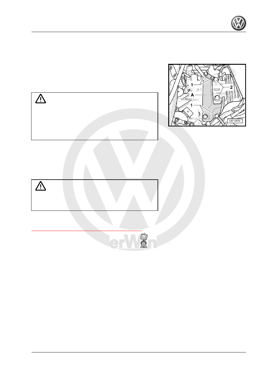
First tighten the bolts -1- when installing the transmission bracket

-A-.
– Align the engine/transmission in its installed position. Lift until

the transmission bracket is touching the transmission mount

completely.

Caution

Risk of damaging threads in transmission bracket by inserting

bolts crooked.

♦ Before installing bolts -2-, transmission bracket and trans‐

mission mount support arm must be absolutely parallel to

each other. If necessary, lift the back of the transmission

with Engine and Transmission Jack .

Adjust the »old fit« between both bolts using a screwdriver when

tightening the transmission bracket to the transmission mount

bolts -2-.
– Check the subframe mount adjustment. If required, adjust.

Refer to ⇒  Engine Mechanical, Fuel Injection and Ignition;

Rep. Gr.  10 ; Subframe Mount; Subframe Mount, Adjusting .

WARNING

Only remove Engine Support Bridge - 10-222A- when all the

left and right subframe mount bolts are tightened to the tight‐

ening specification.

Tightening specification of the transmission on the engine and the

left subframe mount. Refer to

⇒ “3.3 Transmission Tightening Specifications”, page 66

 .

– Install the pendulum support. Refer to ⇒  Engine Mechanical,

Fuel Injection and Ignition; Rep. Gr.  10 ; Subframe Mount;

Overview - Subframe Mount .

– Install the drive axles. Refer to ⇒  Suspension, Wheels, Steer‐

ing; Rep. Gr.  40 ; Drive Axle; Drive Axle, Removing and

Installing .

– Install the heat shield over the right drive axle, if removed. Re‐

fer to ⇒  Suspension, Wheels, Steering; Rep. Gr.  40 ; Drive

Axle; Drive Axle Heat Shield, Removing and Installing .

– Align the exhaust system free of tension. Refer to ⇒  Engine

Mechanical, Fuel Injection and Ignition; Rep. Gr.  26 ; Exhaust

Pipes/Mufflers; Exhaust System, Installing without Tension .

– Install starter. Refer to ⇒  Electrical Equipment; Rep. Gr.  27 ;

Starter; Starter, Removing and Installing .

– Install the charge air hose -A-. Refer to ⇒  Engine Mechanical,

Fuel Injection and Ignition; Rep. Gr.  21 ; Charge Air System;

Overview - Charge Air System .

– Install the Secondary Air Injection Solenoid Valve - N112- .

Refer to ⇒  Engine Mechanical, Fuel Injection and Ignition;

Rep. Gr.  26 ; Secondary Air Injection System; Secondary Air

Injection Solenoid Valve - N112- , Removing and Installing .

– Install the coolant hoses to the ATF cooler according the mark‐

ings made during the removal.

– Attach the selector lever cable to the transmission and adjust

it. Refer to

⇒ “2.4 Selector Lever Cable, Checking and Adjusting”,

page 30

 .

– Install the battery tray and the battery. Refer to ⇒  Electrical

Equipment; Rep. Gr.  27 ; Battery; Overview - Battery .

– Connect the battery and follow the procedure regarding what

to do after connecting a battery. Refer to ⇒  Electrical Equip‐

ment; Rep. Gr.  27 ; Battery; Battery, Disconnecting and

Connecting .

– Check the ATF level. Refer to

⇒ “7 Automatic Transmission Fluid”, page 73

 .

– Install the lower section of the left front wheel housing liner.

Refer to ⇒  Body Exterior; Rep. Gr.  66 ; Wheel Housing Liner;

Front Wheel Housing Liner, Removing and Installing .

– Install the noise insulation. Refer to ⇒  Body Exterior; Rep. Gr. 

66 ; Noise Insulation; Overview - Noise Insulation .

– Install the wheels. Refer to ⇒  Suspension, Wheels, Steering;

Rep. Gr.  44 ; Wheels and Tires; Wheel Bolt Tightening Spec‐

ifications .

– Perform a basic setting. Connect the Vehicle Diagnostic Test‐

er and select “perform basic setting” under 

Guided Func-

tions

.

3.3

Transmission Tightening Specifications

Transmission on a 1.8L - 125 kW - Engine

Note

The -arrows- point to the alignment sleeves in the engine.

When removing and installing pay attention to the different bolt lengths.

In necessary the bolt length may differ from the illustration.

The starter bolts for the starter are M12 x 155 if necessary.

1 - Direction of Travel
M12 - 80 Nm

❑ When the Insert Tool -

18mm - T10179- or In‐

sert Tool - 18mm -

T10509- is used: 65 Nm.

M10 - 40 Nm

❑ The bolts are located in‐

side the lower flange

Left Assembly Mounts
– Replace all the bolts from the left subframe mount.
– Position all the new bolt first by hand.
Tightening Specifications

Component

Tightening Specification

Transmission bracket to trans‐

mission (use new bolts -1-)

40 Nm +90°

Transmission bracket to the

transmission mount (use new

bolts -2-)

60 Nm +90°

Drive plate to torque converter

60 Nm

Coolant hose bracket to the en‐

gine

20 Nm

4

Transmission, Transporting

Special tools and workshop equipment required
♦ Engine/Gearbox Support Shackle (2 pc.) - 10-222A/12-
♦ Shop Crane - VAS6100-
The Engine/Gearbox Support Shackle (2 pc.) - 10-222A/12- can

be used when transporting the automatic transmission and for

setting up the Transmission Support - 3282- .
– Secure the torque converter with wire -A- to prevent it from

falling when being transported.

Note

The torque converter and transmission in the illustration may dif‐

fer from the Original Part.

– Secure the Engine/Gearbox Support Shackle (2 pc.) -

10-222A/12- at the top of the transmission housing.

– Engage the hook of the Shop Crane - VAS6100- into the

shackles as illustrated.

– Lift the transmission with the Shop Crane - VAS6100- and En‐

gine/Gearbox Support Shackle (2 pc.) - 10-222A/12- .


Content   ..  625  626  627  628   ..