Volkswagen Golf / Golf GTI / Golf Variant. Service manual - part 623


  Index      Volkswagen     Volkswagen Golf / Golf GTI / Golf Variant - service and repair manual 2013 year


Search            copyright infringement  


Content   ..  621  622  623  624   ..


Volkswagen Golf / Golf GTI / Golf Variant. Service manual - part 623


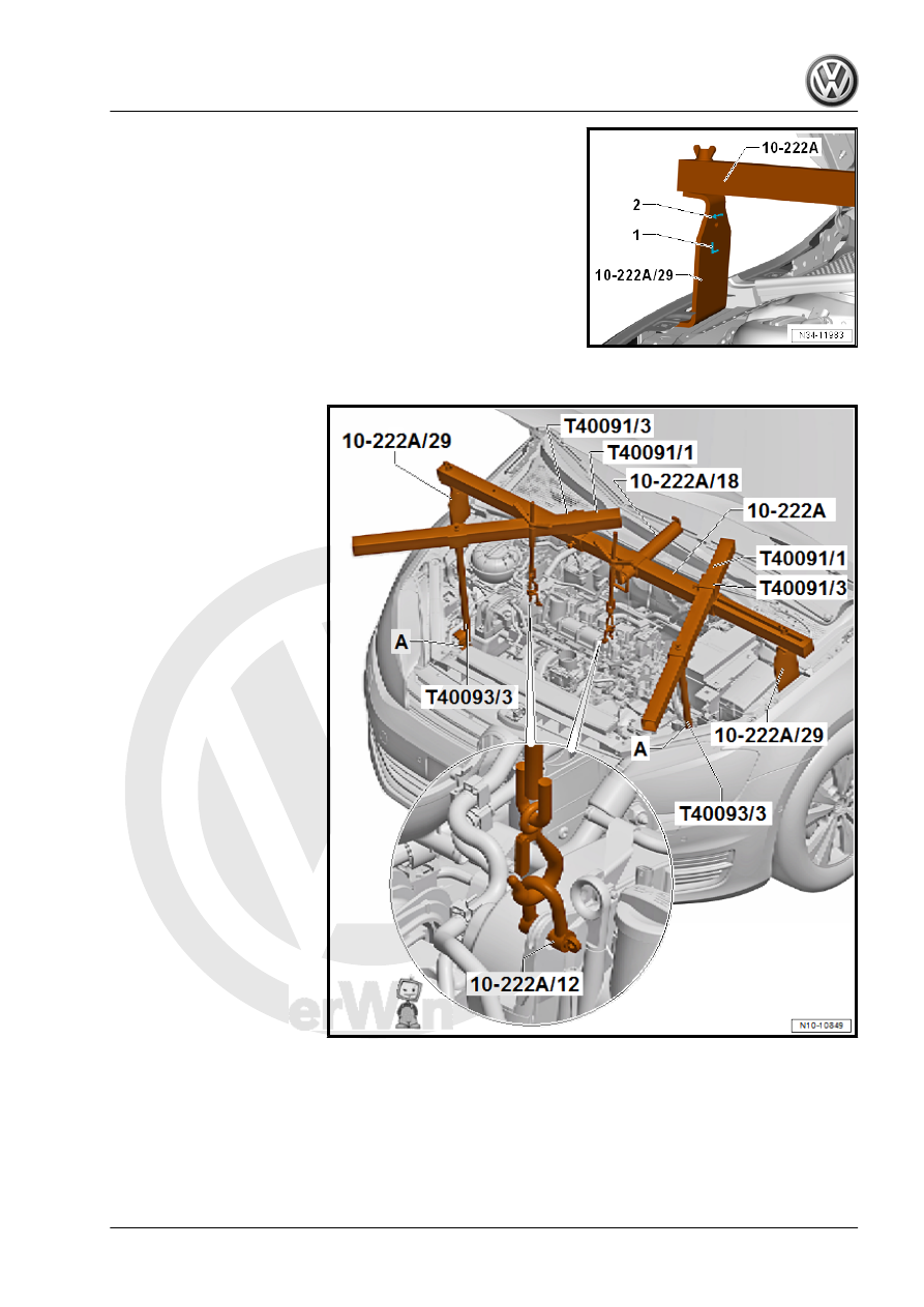
• The arrow -2- on the Engine Support Bridge - Engine Support

29 - 10-222A/29- always points in the direction of travel.

• The Engine Support Bridge - Engine Support 29 - 10-222A/29-

on the load-bearing components of the fender bolting edge.

Assemble the Engine Support Bridge - 10-222A- as follows:

– Slide the Engine Support Bridge - Engine Support 18 -

10-222A/18- and two Engine Support - Basic Set Movable

Joint - T40091/3- onto the Engine Support Bridge - 10-222A- .

– Install the Square Pipe - T40091/1- in the Engine Support -

Basic Set - Movable Joint - T40091/3- .

– Push the Engine Support Bridge - Spindle - 10 - 222 A /11- on

the square pipe -T40091/1-

– Place the Engine Support Bridge - Spindle - 10 - 222 A /11-

on the Engine Support Bridge - Engine Support 18 - 10-222A/

18- .

– Tighten the Engine Support Bridge - 10-222A- on the Engine

Support Bridge - Engine Support 29 - 10-222A/29- .

– Install the Engine/Gearbox Support Shackle (2 pc.) - 10-222A/

12- as shown on the engine.

– Install the Engine Support Brackets - T40093/3-6- -A- as fol‐

lows. (⇒ next illustration).

The adapter -A- is the Engine Support Brackets - T40093/3-6- and

is positioned as follows:
– If present, remove wires from the front area of both longitudinal

members -arrow-. Do not disconnect line system.

– Place the Engine Support Brackets - T40093/3-6- on both lon‐

gitudinal members (the right longitudinal member is illustrated

here).

– If necessary, carefully unclip the A/C system pipe in the front

area. Do not disconnect the line system. Refer to ⇒  Heating,

Ventilation and Air Conditioning; Rep. Gr.  87 ; Refrigerant

Circuit; System Overview - Refrigerant Circuit .

• The Engine Support Brackets - T40093/3-6- locks respectively

with the pins -A- behind the tab on the longitudinal member

-arrow-.

– Install the Engine Support - Supplement Kit Spindle -

T40093/3- .

– Connect the Engine Support - Supplement Kit Spindle -

T40093/3- over the Engine Support - Basic Set Square Pipe -

T40091/1- with the Engine Support Bridge - 10-222A- and

tension it (⇒ previous illustration).

Note

The Engine Support - Basic Set - Square Pipe - T40091/1-

must not touch the windshield.

The Engine Support Bridge - Engine Support 18 - 10-222A/18-

must not lie on the windshield wiper arm.

– Engage the Spindles into the engine lifting eyes using the En‐

gine/Gearbox Support Shackle (2 pc.) - 10-222A/12- .

– Pretension the engine/transmission assembly and Engine

Support Bridge via the Spindles .

– Raise the vehicle and remove the front wheels.
– Remove the noise insulation. Refer to ⇒  Body Exterior; Rep.

Gr.  66 ; Noise Insulation; Overview - Noise Insulation .

– Remove the lower section of the left front wheel housing liner.

Refer to ⇒  Body Exterior; Rep. Gr.  66 ; Wheel Housing Liner;

Front Wheel Housing Liner, Removing and Installing .

– Remove the left and right driveshafts. Refer to ⇒  Suspension,

Wheels, Steering; Rep. Gr.  40 ; Drive Axle; Drive Axle, Re‐

moving and Installing .

– Disconnect the connectors -1- and -2- from the front of the

transmission.

– Open the coolant hose bracket -2- and remove the coolant

hose -3-.

– Unclip the wiring harness -arrow-.
– Remove the bolts -4- from the engine and remove the bracket

-1-.

– Remove the three converter nuts -arrow- through the opening

in the intermediate plate using the Storage Compartment Cen‐

tral Locking Motor - V/175- .

– To do this, turn the engine 120° further in the direction of en‐

gine rotation at the belt pulley/vibration damper.

Note

The torque converter will be pulled out when the transmission is

separated from the engine if all three nuts are not removed!

– Remove bolts -1 through 3- and remove pendulum support.

– Remove the bracket bolts -arrows- for the exhaust system on

the subframe.

– Remove the bolts -2- that attach the transmission mount to the

transmission bracket -A- and the bolts -1- that attach the trans‐

mission bracket to the transmission.

– Remove the transmission bracket -A-. Lower the engine with

the transmission slightly using the spindles on the Engine

Support Bridge .

Four turns should be sufficient.

– Remove the lower bolts -5 to 7- between the engine and the

transmission.

Note

The rear bolts -8- and -9- that connect the engine to the trans‐

mission remain installed.


Content   ..  621  622  623  624   ..