Volkswagen Golf / Golf GTI / Golf Variant. Service manual - part 616
11 - Selector Lever Cable
❑ Removing and installing. Refer to
⇒ “2.3 Selector Lever Cable, Removing and Installing”, page 27
12 - Clips
❑ Secures the selector lever cable on the cable bracket
❑ Replace after removing
13 - Bolt
❑ 20 Nm
14 - Clips
❑ Replace after removing
2.2
Selector Mechanism, Removing and In‐
stalling
⇒ “2.2.1 Shift Mechanism with Selector Lever Cable, Removing
and Installing”, page 21
⇒ “2.2.2 Selector Mechanism without Selector Lever Cable, Re‐
moving and Installing”, page 24
2.2.1
Shift Mechanism with Selector Lever
Cable, Removing and Installing
Caution
This procedure contains mandatory replaceable parts. Refer
to component overview prior to starting procedure.
Mandatory Replacement Parts
♦ Clip - Selector Lever Cable to the Cable Bracket
♦ Clip - Selector Lever Cable to the Selector Mechanism
♦ Plug - Selector Mechanism
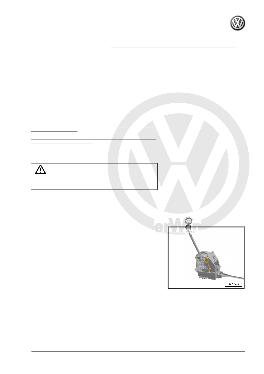
Short Description
Remove the center console inside the passenger compartment.
It is necessary to remove the heat shield under the vehicle.
Removing