Volkswagen Golf / Golf GTI / Golf Variant. Service manual - part 598


  Index      Volkswagen     Volkswagen Golf / Golf GTI / Golf Variant - service and repair manual 2013 year


Search            copyright infringement  


Content   ..  596  597  598  599   ..


Volkswagen Golf / Golf GTI / Golf Variant. Service manual - part 598


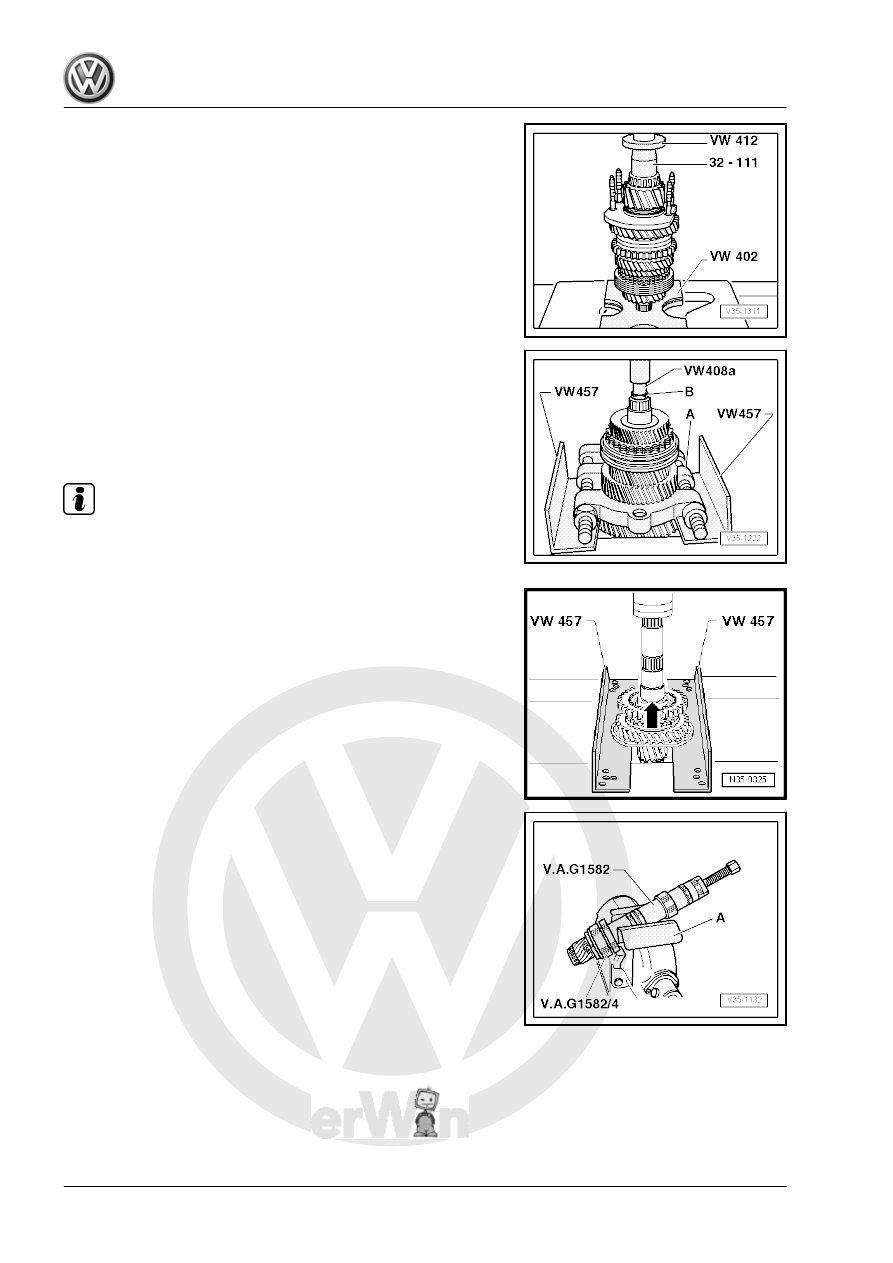
Installing the Inner Race/Small Tapered Roller Bearing

Removing the 3rd/4th Gear Synchronizer Hub/Locking Collar,

2nd Gear Wheel, 3rd and 4th Gear with Output Shaft Needle

Bearing Sleeve
A - Puller - Quick Action Separating Tool - 22-115mm - Kukko

17/2- , for example.
B - M10 x 20, 17 mm Hex Bolt

Note

Support the separating tool so that the 1st/2nd gear locking collar

does not come off as well.

Removing the Locking Collar with the Synchronizer Hub and

Bearing Mount
– Remove the locking ring -arrow- beforehand.

Removing the Inner Race/Large Tapered Roller Bearing
-A- vise protectors
– Before installing puller, insert a M10 x 20 bolt into the hole in

the output shaft.

Installing the Inner Race/Large Tapered Roller Bearing
-A- thrust washer
– Install the thrust washer before installing the inner race. The

shoulder faces the inner race.

Installed Position of the Inner Race, the Outer Race and the 1st

Gear Synchronizer Ring
– Place inner race -A- on drive gear for 1st gear.
The angled tabs -arrow 1- face the outer race -B-.
– Install the outer race -B-.
The tabs -arrow 2- must lock into the retainers -arrow 3- in the

gear wheel.
– Install the synchronizer ring -C-.
The retainers -arrow 4- lock in the tabs -arrow 1- on the inner race

-A-.

Note

If the parts are not to be replaced, make sure they are reallocated

to their original gear.

Checking Inner Race for 1st Gear and 2nd Gear for Wear
– Install the inner race onto taper of selector gear and then

measure gap dimension -a- with a feeler gauge.

Gap Dimension

-a-

Installation Dimen‐

sion

Wear Limit

1st and 2nd gear

0.75 to 1.25 mm

0.3 mm

Checking 1st Gear and 2nd Gear Synchronizing Ring for Wear
– Install the synchronizer ring, outer race and inner race onto

taper of selector gear and then measure the gap dimension

-a- with a feeler gauge.

Gap Dimension

-a-

Installation Dimen‐

sion

Wear Limit

1st and 2nd gear

1.2 to 1.8 mm

0.5 mm

Disassembling and Assembling Locking Collar and Synchronizer

Hub for 1st and 2nd Gears
1 - Spring
Spring allocation. Refer to the Parts Catalog.
Assembly in conjunction with hollow locking pieces. Refer to

⇒ Fig. ““Assembly: Locking Collar/Synchronizer Hub for 1st and

2nd Gears Together with Locking Pieces That Are Hollow on the

Inside”“ , page 162

 .

Assembly in conjunction with locking pieces that are not hollow.

Refer to

⇒ Fig. ““Assembly: Locking Collar/Synchronizer Hub for 1st and

2nd Gears Together with locking Pieces That Are Not Hollow”“ ,

page 162

 .

2 - Locking collar
3 - Synchronizer Hub
4 - Locking piece
Allocate the locking pieces. Refer to the Parts Catalog.
The collar has the same width on both side of the synchronizer

hub.
The Shoulder Has a Chamfer on One Side -arrow B-
The bevel on the synchronizer hub collar and the splines on the

outside of the locking collar -arrow A- face in the same direction

after being assembled.
The notches on the synchronizer hub and locking collar for the

locking pieces -arrow C- must line up.

Assembly: Locking Collar/Synchronizer Hub for 1st and 2nd

Gears Together with Locking Pieces That Are Hollow on the In‐

side
• The locking collar is pushed over the synchronizer hub.
– Install the locking pieces and springs offset by 120°. The an‐

gled end of the spring must engage into the hollow locking

piece.

Assembly: Locking Collar/Synchronizer Hub for 1st and 2nd

Gears Together with locking Pieces That Are Not Hollow
• The locking collar is pushed over the synchronizer hub.
– Install the locking pieces and springs offset by 120°.
• The angled end of the spring must be positioned in front of the

locking pieces -arrows-.

Installed Position: Locking Collar/Synchronizer Hub for 1st and

2nd Gears
The teeth of the locking collar -arrow- point toward the splines of

the 3rd/4th gear synchronizer hub -A-.

Installing the Locking Collar/Synchronizer Hub for 1st and 2nd

Gears.
Turn the synchronizer ring so that the grooves line up with the

locking pieces.

Installed Position of 2nd Gear Outer Race
The tabs -arrows- face 1st gear -A-.

Installed Position: Synchronizer Ring -A- (2nd Gear Inner Race)
The tabs -arrow 1- engage into the holes -arrow 2- inside the

synchronizer ring -B-.


Content   ..  596  597  598  599   ..