Volkswagen Golf / Golf GTI / Golf Variant. Service manual - part 587


  Index      Volkswagen     Volkswagen Golf / Golf GTI / Golf Variant - service and repair manual 2013 year


Search            copyright infringement  


Content   ..  585  586  587  588   ..


Volkswagen Golf / Golf GTI / Golf Variant. Service manual - part 587


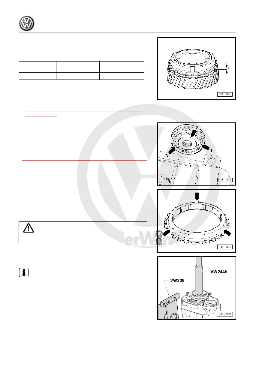
Checking 5th Gear Synchronizer Ring
– Before re-installing the gear wheel and the 5th gear synchron‐

izer ring push the synchronizer ring onto the taper of the drive

gear. Measure the gap dimension -a- with a feeler gauge.

Gap Dimension

-a-

Installation Dimen‐

sion

Wear Limit

5th Gear

1.1 to 1.7 mm

0.5 mm

– Install 5th gear wheel with needle bearing.
– Place the 5th gear synchronizer ring onto the selector gear.
– If disassembled, assemble the 5th gear synchronizer hub/

locking collar before installing. Refer to

⇒ Fig. ““5th Gear Locking Collar/Synchronizer Hub Assem‐

bly”“ , page 147

 .

Installed Position of 5th Gear Synchronizer Hub/Locking Collar
The pointed teeth on the locking collar -arrow 1- and the high col‐

lar on the synchronizer hub -arrow 2- face the transmission hous‐

ing.
The notches -arrow 3- on the synchronizer hub must line up with

the cast locking pieces on the synchronizer ring

⇒ Fig. ““5th Gear Synchronizer Ring with Cast Locking Pieces”“ ,

page 116

 lower).

5th Gear Synchronizer Ring with Cast Locking Pieces
– Cover all openings with a cloth to prevent foreign objects from

getting into the transmission.

– To install, heat the 5th gear synchronizer hub to approximately

100 °C (212 °F) with the Inductive Heater - VAS6414- .

WARNING

Wear safety gloves.

– Install the 5th gear synchronizer hub

Note

Make sure there is enough clearance when installing the syn‐

chronizer ring.

– Loosen the support for the input shaft.
If it has not been done already, locking fluid residue from the

threaded holes for the synchronizer hub bolts and 5th gear wheel

must be cleaned with a thread tap.
Otherwise, there is the danger that the bolts could shear off.
– Screw-in new synchronizer hub bolts and 5th gear wheel.

Installed Position of Plate Springs for 5th Gear Synchronizer Hub

and Gear Securing Bolts
The outer diameter -arrows- faces 5th gear.

– Engage 5th gear -arrow 1- and 1st gear -arrows 2 and 3- and

then tighten the bolts -A- for the synchronizer hub and for the

5th gear wheel.

– The input shaft and the output shaft are blocked after both

gears are engaged. The synchronizer hub and the gear wheel

cannot turn. Both bolts can be loosened now.

– Install the 5th gear shift fork.

Pro

te

c

t

ed

  b

y

  co

p

y

rig

h

t. 

C

o

p

y

in

g

  fo

pr

iv

a

t

e

 o

r

 c

o

m

m

e

r

c

ia

p

u

rp

o

s

e

s

,

 i

n

 p

a

rt

o

r i

n

 w

h

o

le

is

 n

o

t

 p

e

r

m

it

t

e

d

 u

n

l

e

s

s

 a

ut

ho

r

i

s

ed

 b

y

 V

olk

sw

a

ge

n AG

.


V

olk

s

w

a

g

en

 AG do

es 

n

ot g

uar

ante

e

 or a

c

c

ep

t

 a

ny


li

a

b

i

li

t

y

 w

ith

 r

e

s

p

e

c

t

 t

o


th

e

 c

o

rr

e

c

t

n

e

s

s


o

f

in

fo

r

m

a

tio

n

 in

 th

is

 d

o

c

um

en

t.

C

o

py

rig

ht b

y


V

olk

sw

a

ge

n


A

G.

Adjusting 5th Gear
– Engage 5th gear. Loosen the bolt -1-. Push the locking collar

and the shift jaw in direction of -arrow-. Tighten the bolt -1- to

the tightening specification.

• Check measurement: it must not be possible to slide a 0.2 mm

feeler gauge between the locking collar and drive gear. Repeat

the adjusting procedure if necessary.

– Remove 5th gear. The locking collar must be in the neutral

position. The synchronizer ring must move freely.

– Move the gearshift lever (selector lever) through all the gears.
– Install the transmission housing cover. Refer to

⇒ “5.3 Overview - Transmission Housing Cover and 5th Gear”,

page 93

 .

– Install the release bearing guide sleeve. Refer to

⇒ “1.4 Overview - Clutch Release Mechanism”, page 18

 .

– Install the clutch release lever and release the bearing. Refer

to 

⇒ “1.16 Clutch Release Mechanism, Servicing”, page 35

 .

– Fill the transmission fluid. Refer to 

⇒ page 78

 .

Tightening Specifications
♦ Refer to

⇒ “5.3 Overview - Transmission Housing Cover and 5th Gear”,

page 93

♦ Refer to 

⇒ “5.7 Overview - Shift Forks”, page 98

 .

6

Transmission Housing and Clutch

Housing

⇒ “6.1 Overview - Transmission Housing and Clutch Housing”,

page 119
⇒ “6.2 Transmission Housing, Servicing”, page 121
⇒ “6.3 Clutch Housing, Servicing”, page 122

6.1

Overview - Transmission Housing and Clutch Housing

1 - Transmission Housing

❑ When replacing: adjust

the input shaft and dif‐

ferential. Refer to

⇒ “3 Adjustment Over‐

view”, page 198

2 - Needle Bearing

❑ For the output shaft
❑ Removing. Refer to

⇒ Fig. ““Removing the

Needle Bearing”“ , page

121

 .

❑ Installing and securing.

Refer to

⇒ Fig. ““Installing the

Needle Bearing”“ , page

121

3 - Transmission Fluid Filler

Plug

❑ 35 Nm
❑ The transmission fluid

level cannot be checked

by removing oil filler

plug.

❑ If transmission was dis‐

assembled, it must be

filled before being instal‐

led again.

❑ Manual transmission

capacity (transmission

completely disassem‐

bled). Refer to ⇒  Fluid

Capacity Tables; Rep.

Gr.  03

❑ Manual transmission

capacity (transmission

partly disassembled). Refer to ⇒  Fluid Capacity Tables; Rep. Gr.  03

4 - Outer Race/Tapered Roller Bearing

❑ For the output shaft
❑ Refer to 

⇒ “2.2 Output Shaft, Disassembling and Assembling”, page 158

❑ When replacing: adjust the output shaft. Refer to 

⇒ “2.3 Output Shaft, Adjusting”, page 166

 .

5 - Shim

❑ For the output shaft
❑ Adjustment overview. Refer to 

⇒ “3 Adjustment Overview”, page 198

 .

6 - Shim

❑ For the input shaft


Content   ..  585  586  587  588   ..