Volkswagen Golf / Golf GTI / Golf Variant. Service manual - part 513


  Index      Volkswagen     Volkswagen Golf / Golf GTI / Golf Variant - service and repair manual 2013 year


Search            copyright infringement  


Content   ..  511  512  513  514   ..


Volkswagen Golf / Golf GTI / Golf Variant. Service manual - part 513


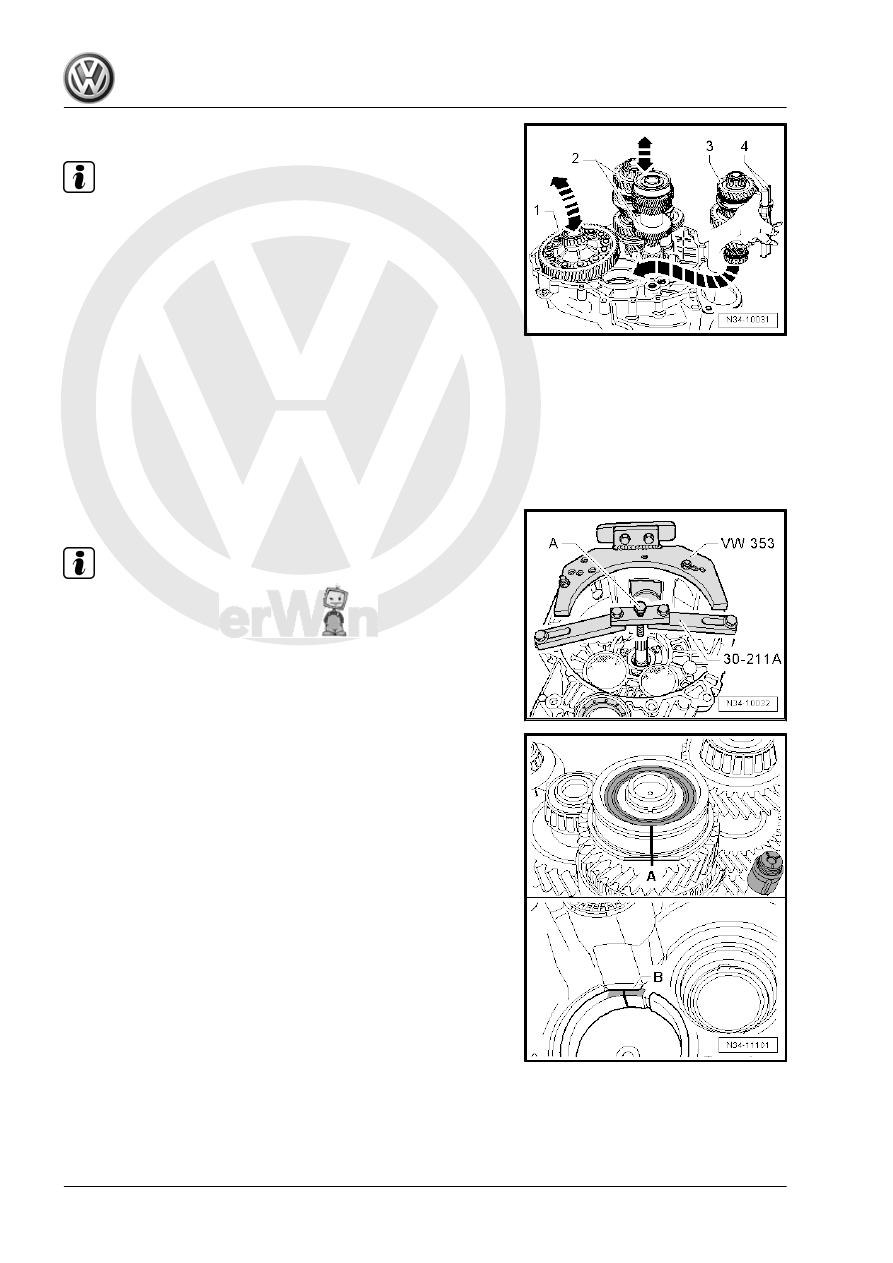
– Then install the differential -1-.

Note

A second technician is needed to help install the shafts into the

clutch housing.

– Hold 1st through 4th gear output shaft -3- with the shift lever

rods -4- in the right hand as illustrated.

– Lift the differential slightly with your left hand.
– Have the second technician lift the input shaft, the 5th/6th gear

output shaft -2- together with the reverse shaft slightly at the

same time.

– Install the 1st through 4th gear output shaft in direction of

-arrow-.

• Places of input shaft, output shafts and final drive gear/differ‐

ential must engage.

– Place the shafts and the differential in their bearing seats with

a second technician.

– Secure the -30-211A- for the input shaft to the clutch housing.

Note

The clutch housing is shown in the illustration rotated 180°.

– Install the bolt -A- just far enough until the input shaft starts to

lift.

The Grooved Ball Bearing/Input Shaft Only Fits In One Position

In the Transmission Housing.
There is a flattened area on the grooved ball bearing and the

bearing mount.
• The flattened sides -A- on the grooved ball bearing and on the

bearing mount -B- must align in the transmission housing.

– Mark this flat side with color.
– Transfer the markings to the upper area of the grooved ball

bearing and to the upper area of the transmission housing

bearing mount (⇒ next figure).

– Heat the transmission housing in the area near the bearing

seat for the grooved ball bearing/input shaft to approximately

100 °C (212 °F) for approximately 10 minutes using a Hot Air

Blower , for example, -VAG1416- .

Note

It is necessary to heat the transmission housing so that the

grooved ball bearing is not damaged when the housing is be‐

ing installed.

Apply Sealing Paste - AMV 188 200 03- evenly onto the seal‐

ing surface of the clutch housing.

Align the marking on the grooved ball bearing -A- with the

marking on the transmission housing -B- and mount the trans‐

mission housing.

– Install the transmission housing and tighten the new bolts

-A, B and C-.

The Circlip -1- for the Grooved Ball Bearing/Input Shaft -2- Must

Be Re-Examined on Transmissions with Reinforcements (manual

transmission 0FB):
• Check that the input shaft with the -30-211A- is pressed up

against the transmission housing.

• Identify the thickest circlip for the grooved ball bearing/input

shaft that has not yet been used and install it, starting with the

thickest circlip.

The following circlips are available. Refer to the Parts Catalog for

the part number.

Circlip Thickness (mm)

2.03

2.09

2.15

2.21

2.27


Continuation for All

– Install the grooved ball bearing/input shaft locking ring -1-.
– Remove the -30-211A- for the input shaft.
– If the retaining sleeve for the shift lever shaft was removed,

then install it now all the way onto the tool. Refer to

⇒ Fig. ““Lock Sleeve Differentiation”“ , page 136

 .

– Turn the transmission so that the opening for the shift lever

shaft faces up in the assembly stand.

Note

Use the -80-200- to press against the spring force of the securing

bushing direction of -arrow- when installing so that the shift lever

shaft -1- does not touch the securing bushing -2- when removing.

– Install the shift lever shaft -1- into the lower bearing -2- and

into the shift forks -3-.

Note

The cover is not shown in the illustration. Refer to

⇒ “6.1 Overview - Transmission Housing”, page 130

 .

– Push the shift lever shaft -1- against the retaining sleeve -2-

in direction of -arrow- and guide is through the shift fork all the

way down using the shift finger -3-.

• The shift lever cover -4- must stand parallel to the bolting sur‐

face on the transmission housing.

• It must be possible to move the shift lever shaft easily (forward

and backward).

Note

If the gearshift cover is at an angle to the bolting surface, then the

gearshift shaft is not installed in the lower bearing.

– Tighten the bolts -3- for the shift lever cover -4-.
– Install the locking bolt -2-, lock elbow -arrow- must not be in‐

stalled when doing so.

– Install the Back-Up Lamp Switch - F4- -1-.

– Transmission for vehicles with start/stop system: Insert the

Transmission Neutral Position Sensor - G701- -arrow- and

tighten the bolt.

– Install the input shaft seal so that it is flush.
– Install the clutch slave cylinder with release bearing. Refer to

⇒ “1.11 Clutch Slave Cylinder with Release Bearing, Remov‐

ing and Installing”, page 33

 .

– Move the shift lever (selector lever) through all the gears.
– Install the cover as follows:

Cover Differentiation
-I- is a metal cover; secured with securing ring -A-.
-II- is a plastic cover; without securing ring.


Content   ..  511  512  513  514   ..