Volkswagen Golf / Golf GTI / Golf Variant. Service manual - part 499
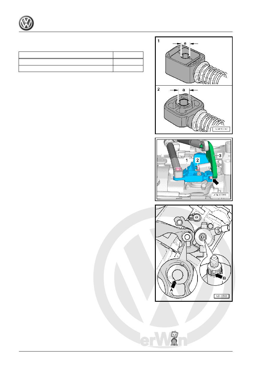
Cable Retainer Allocation
These holes have different diameters.
Cable Retainer for:
Dimension “a”
-1-: Shift cable to shift lever
8.5 mm
-2-: Selector cable to relay lever
10 mm
Selector Lever/ Relay Lever Installed Position
1 - Selector Lever
2 - Clip
3 - The relay lever grips into the sliding rail on the gearshift lever
via the sliding shoe -arrow-.
Installing the Transmission Shift Lever
– When positioning the transmission shift lever, make sure the
tooth gap -arrow A- is placed over the missing selector shaft
teeth -arrow B-.